wing (Intel NUC Skull Canyon NUC6i7KYK)


Summary
A slightly beefy NUC. I got it for doing video capture, and because it has a thunderbolt port.
Notes
- Would not power from my thunderbolt dock
- All the USB ports of the H170 hang on a single hub (shared bandwidth)
- Sometimes the thunderbolt dock doesn't init properly on boot. Haven't been able to work out a pattern yet.
Hardware
| Make | Intel |
| Year | 2016 |
| Model | NUC6i7KYK |
| Chassis | NUC Skull Canyon UCFF |
| Power Supply | 19V 6.32A |
| Processor | Intel Core i7-6770HQ |
| Memory | 16GB DDR4 2666 (Transcend TS1GSH64V6B) |
| Ports | 3.5mm Line Out / Optical Out |
| RJ-45 LAN | |
| 2x USB A 3.0 | |
| Mini DisplayPort 1.2 | |
| ThunderBolt 3 | |
| HDMI 2.0 | |
| SD Card slot | |
| 2x USB A 3.0 (Front) | |
| 3.5mm Headset | |
| Infrared Receiver | |
| Graphics | Intel Iris Pro 580 |
| Storage | 256GB Transcend TS256GMTS800 SSD |
| Display | - |
| Int. Peripherals | Intel I219-LM Gigabit Ethernet |
| Intel Dual Band Wireless-AC 8260 | |
| Ext. Peripherals | ThinkPad Thunderbolt 3 Dock |
| Dimensions | |
| Length/Depth | 21.1 cm |
| Width | 11.6 cm |
| Height/Thickness | 6.6 cm |
| Weight | 1.09 kg (2 lb 6.4 oz) |
Software
| Operating System | Debian 12 |
| Unique applications |
Links
- Technical Product Specs (HTML)
- Technical Product Specs (PDF)
- How to Customize the Splash Screen Image on Intel® NUC (Note special instructions for NUC6i7KYK, only use VCUST)
- Thinkpad Thunderbolt 3 Dock
Log
Crestron UC-ENGINE
I got a Crestron UC-Engine kit. It is for Teams/Skype video conferencing. My (used) set came with:
- UC-ENGINE (NUC6i7KYK, i7-6770HQ, 8GB, 256GB, Win 10 IOT Enterprise)
- HD-CONV-USB-200 (USB 3.0 HDMI Capture, ONLY 1920x1080 Uncompressed)
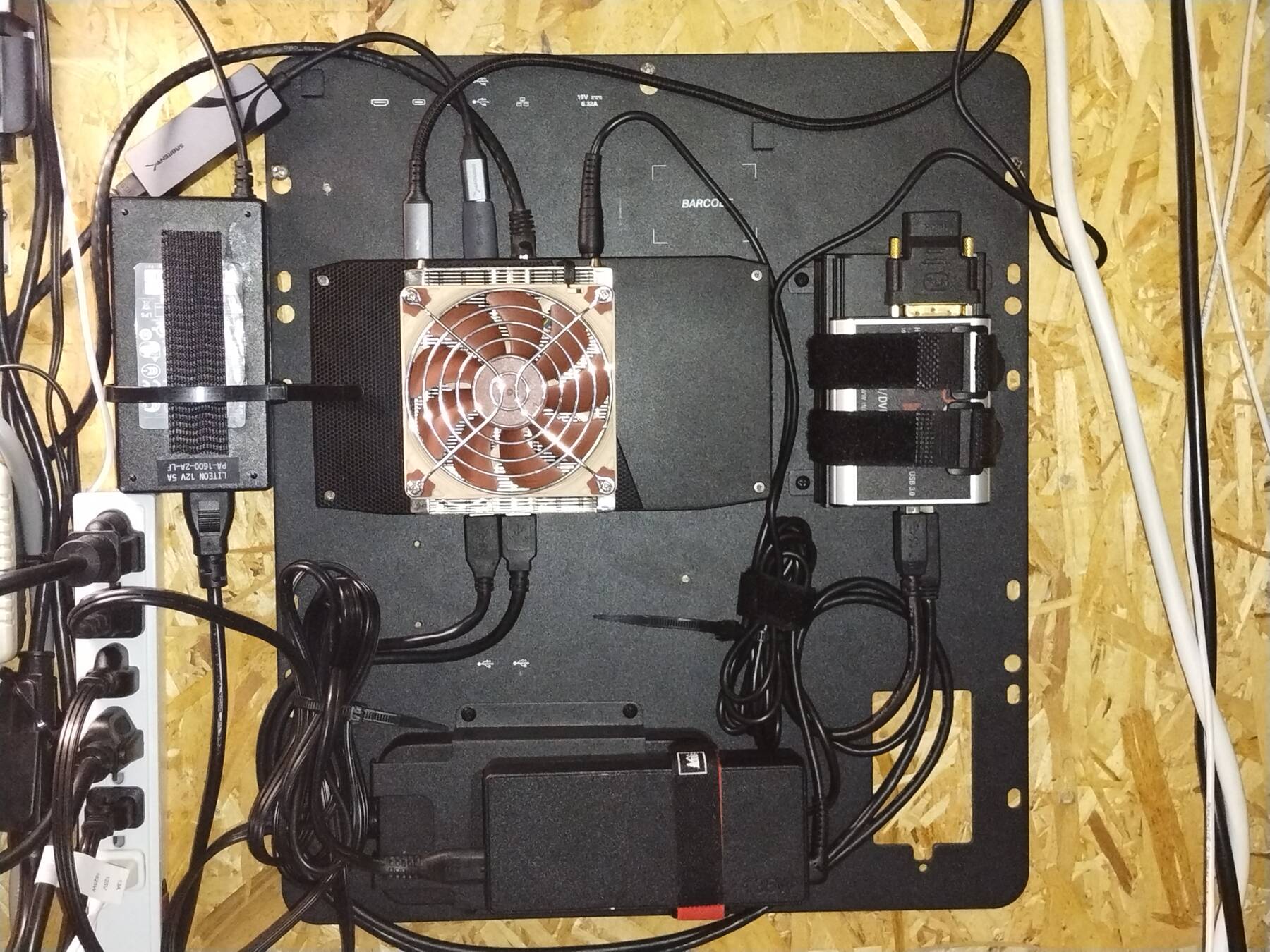
- UC-BRKT-100 (35.5x41cm wall mounting plate)
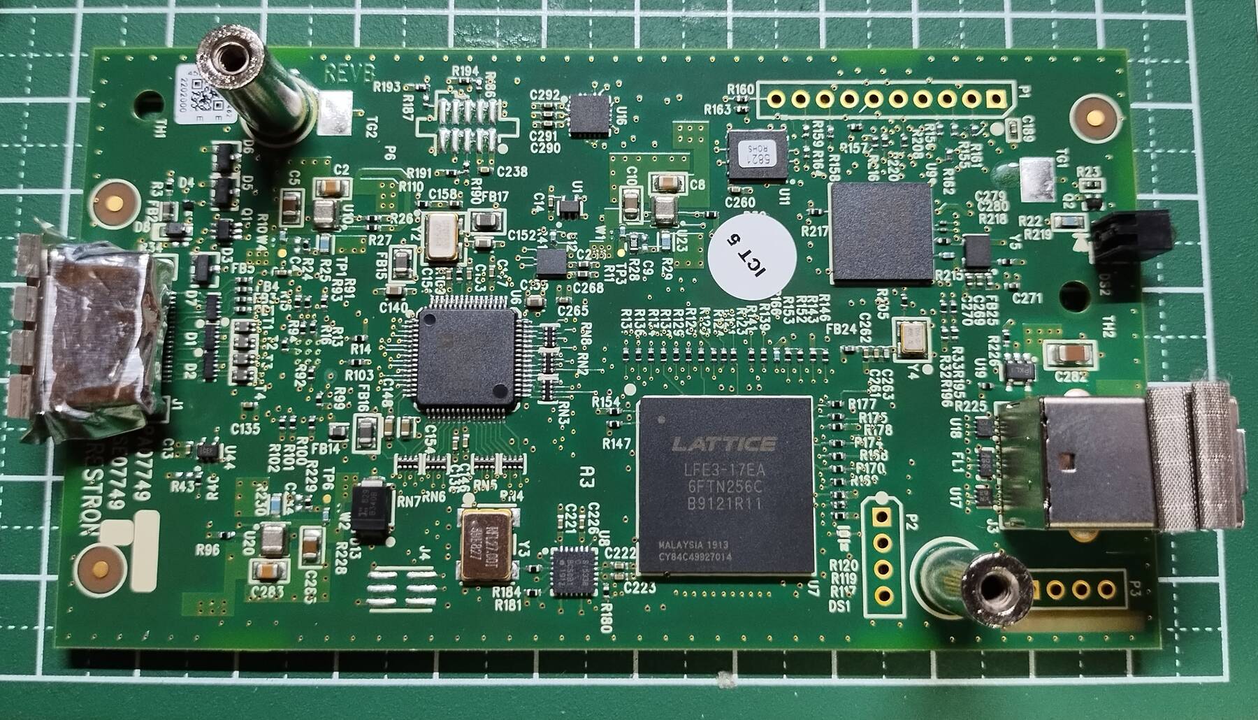
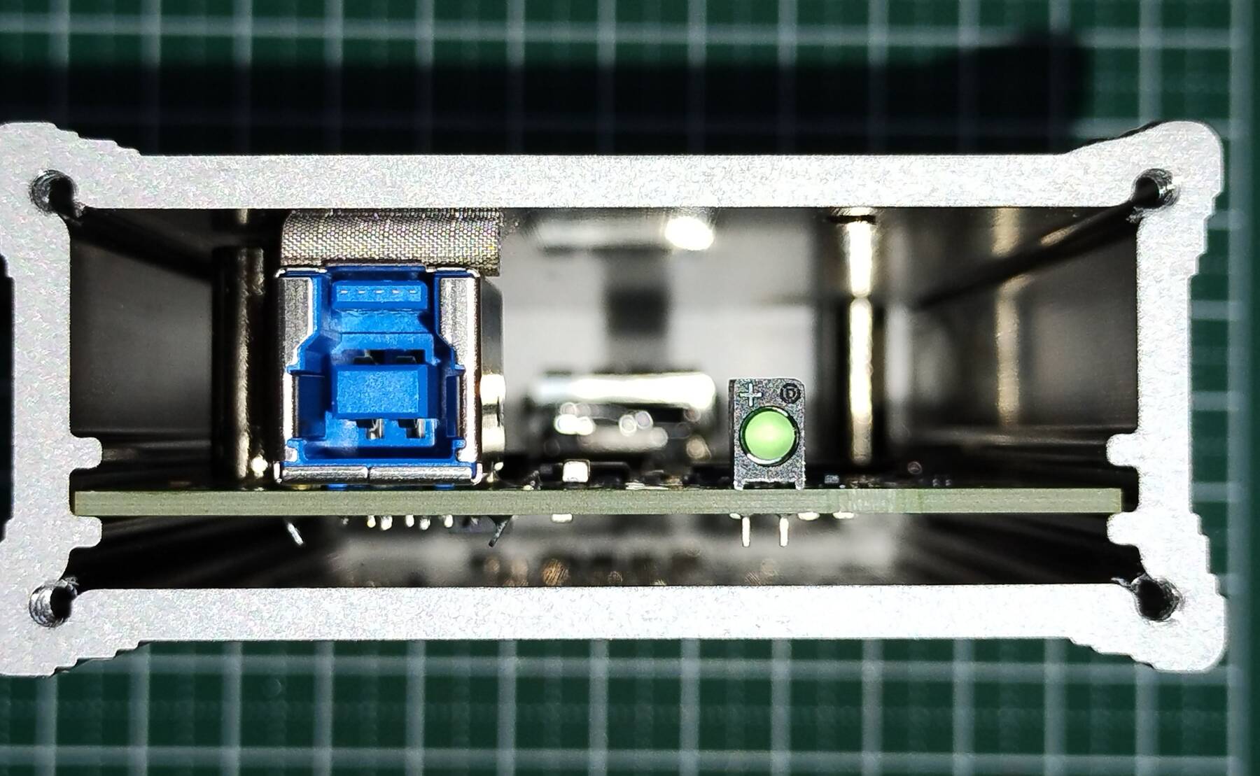
- Capture device (Crestron HD-CONV-USB-200)
First, I was curious about the capture device. The earlier Crestron HD-CONV-USB-100 has a case very similar to Epiphan's DVI2USB 3.0, so I thought they might be repackaging those devices. After opening the 200, I think it is an original design. Comes in a super sturdy aluminum case.
I also looked into the earlier HD-CONV-USB-100 a little more, and I think it cannot be the Epiphan DVI2USB 3.0.
- It is limited to 1280x720 and 1920x1080, the Epiphan has no such limitation
- DVI2USB 3.0 actually supports VGA input, and quite a good range
- DVI2USB 3.0 has lots of interesting configurable settings
I'd still pick one up for maybe $10, but it doesn't seem to be anything special.
I noted some of the chips:
- Parade PS8407A
- HDMI 1.4b retimer for jitter removal
- Analog Devices ADV7611
- Low Power 165 MHz HDMI 1.4a Receiver
- Silicon Labs Si5338
- Any output quad clock generator
- Lattice LFE3-17EA
- Lattice ECP3 FPGA
- Infineon CYUSB3014-BZX
- Infineon/Cypress EZ-USB FX3 (USB 3.2 gen1)
The EZ-USB FX3 has a HDMI-to-USB3 demo kit, but it relies on Lattice ECP5 FPGA. The Crestron isn't a direct copy of that.
Since it is limited to 1920x1080 I will use it to capture camera outputs. I think it can at least cope with common refresh rates so one of my cameras is bound to work.
- NUC BIOS and Boot Logo
I updated the BIOS, and attempted to remove the Crestron boot logo, but ran into some trouble. Intel has a guide: How to Customize the Splash Screen Image on Intel® NUC.
First I tried the Intel Integrator Toolkit. You enable UEFI shell. Boot it, and run the downloaded EFI program from a USB stick (original logos are included to choose from). It creates a BIOS file that you load like a normal BIOS update. This had no effect.
The other tool, Intel VCUST, was not available any more. Both Intel, and Asus pages tell you to contact support to get it. I used the wayback machine, and a link I found on reddit to get to the download: Intel VCUST 1.0.0 on Wayback Machine.
If you pay closer attention than me you'll note there are special instructions for some NUC models, including NUC6i7KYK. (I wasted time doing it twice). You have to pass a valid existing firmware image, and it flashes the whole BIOS rather than the minimal image like other devices.
VCUST is a windows tool. With the UC-ENGINE you can probably get into the Windows admin account by booting it without internet. Eventually it will prompt you to enter Settings. The default admin password is 'sfb' (skype for business). In there is a option for 'Windows Settings' that will take you to a login where you can choose the Administrator, and enter the password again. It seems like you get free reign from there.
I copied the VCUST file, images, and the latest firmware image to the main drive. Then I ran CMD as administrator, and entered:
C:\VCUSTW64.EXE -BIO=C:\KY0074.bio -LOGO=C:\Intel_Default_Splash_Screen\NUC\Intel_NUC_Default_512x384.jpg
The screen went blank except for the cursor, and rebooted after a bit. On reboot you get a prompt, press 9 to approve, and it flashes the complete BIOS (rather than just the image update for other models).
Finally I had the original 'Intel NUC' boot logo.
- Linux install
I put Debian 12 on it. Nothing eventful happened.
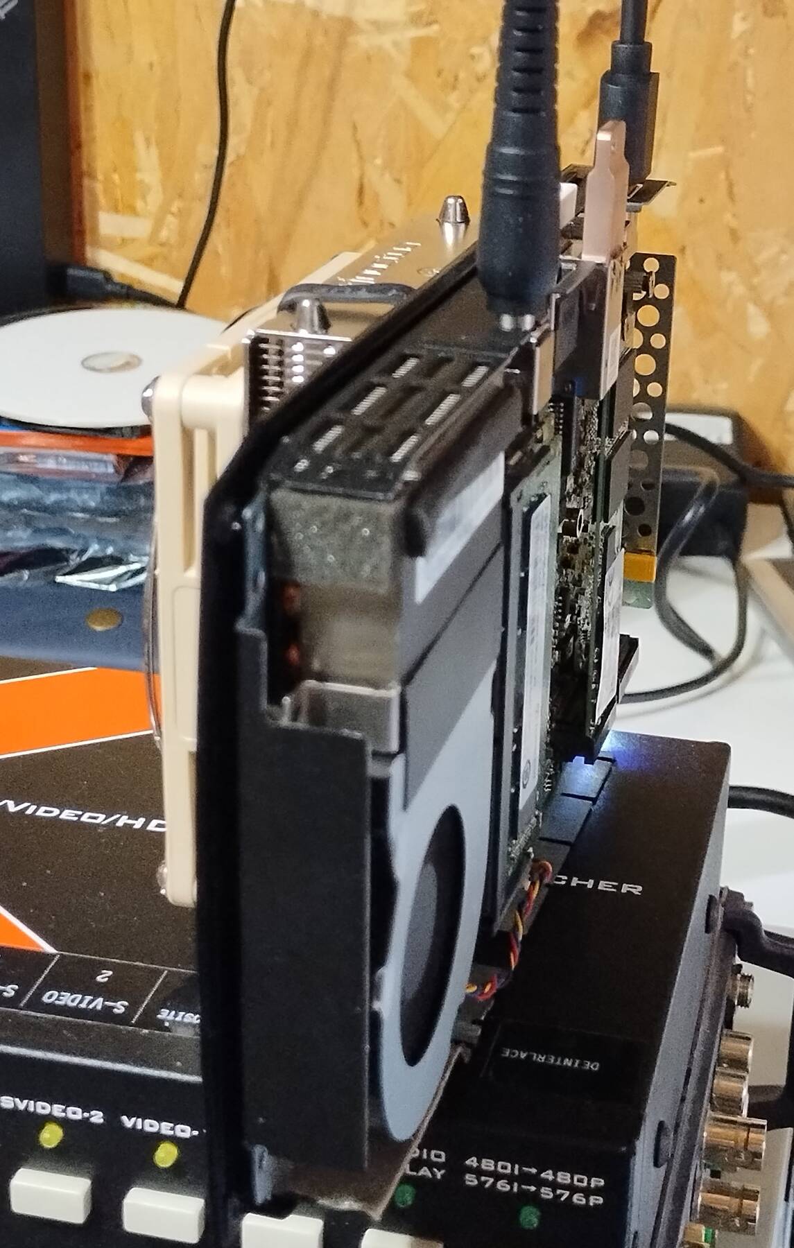
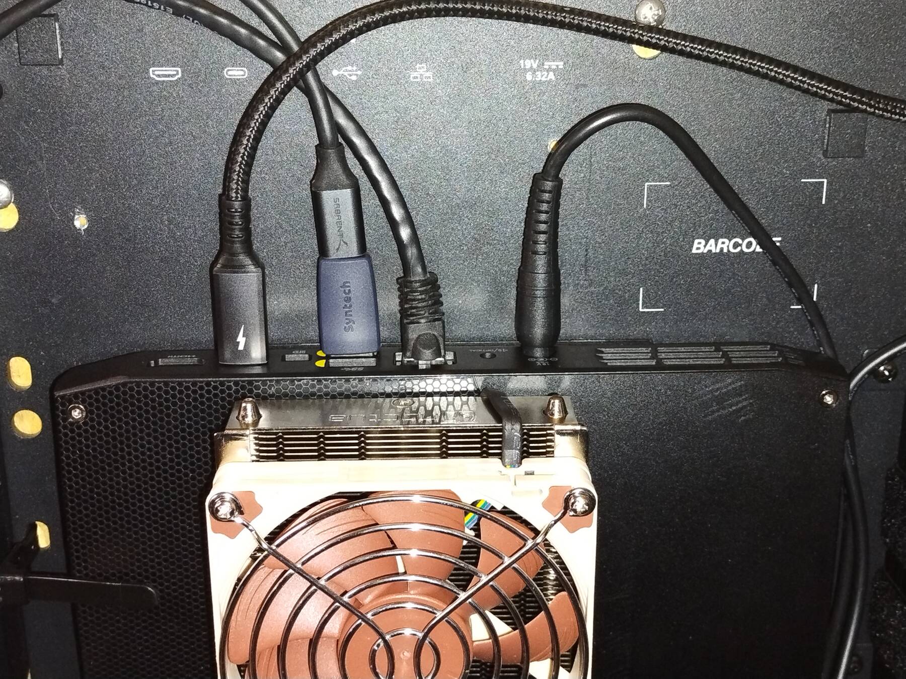
The fan is noisy. Definitely going to look into alternative cooling solutions. Some people cut a hole in the top of the case, and glued a heatsink on top of the CPU side of the heat pipes. Not sure what is out there for fan replacements.
I think the Crestron wall mount plate is pretty cool, and I want to mount it near my video rack noise allowing. It has space for the NUC, power supply, HDMI capture, and an unknown fourth device. There are also two hinged covers to protect/hide the NUC ports and cables, but I'll probably leave them off.
RAM upgrade
I put the old Transcend 8GB (DDR4-2666) sticks from pixy in this to give it 16GB. That's probably enough for my use, and a slight speed bump from 2400.
I ran some dhewm3, and quake4 and things are feeling stable.
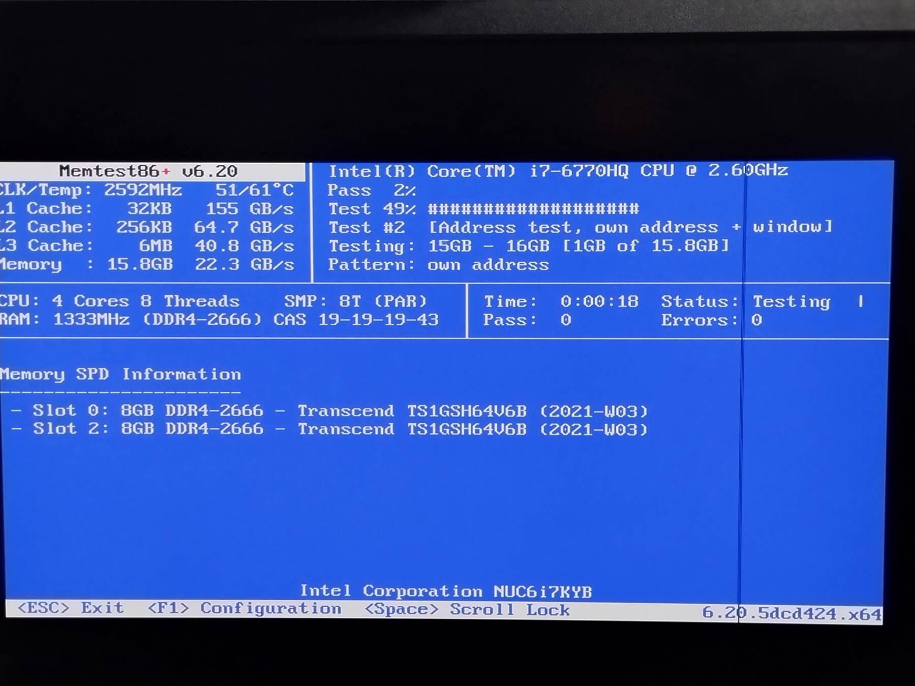
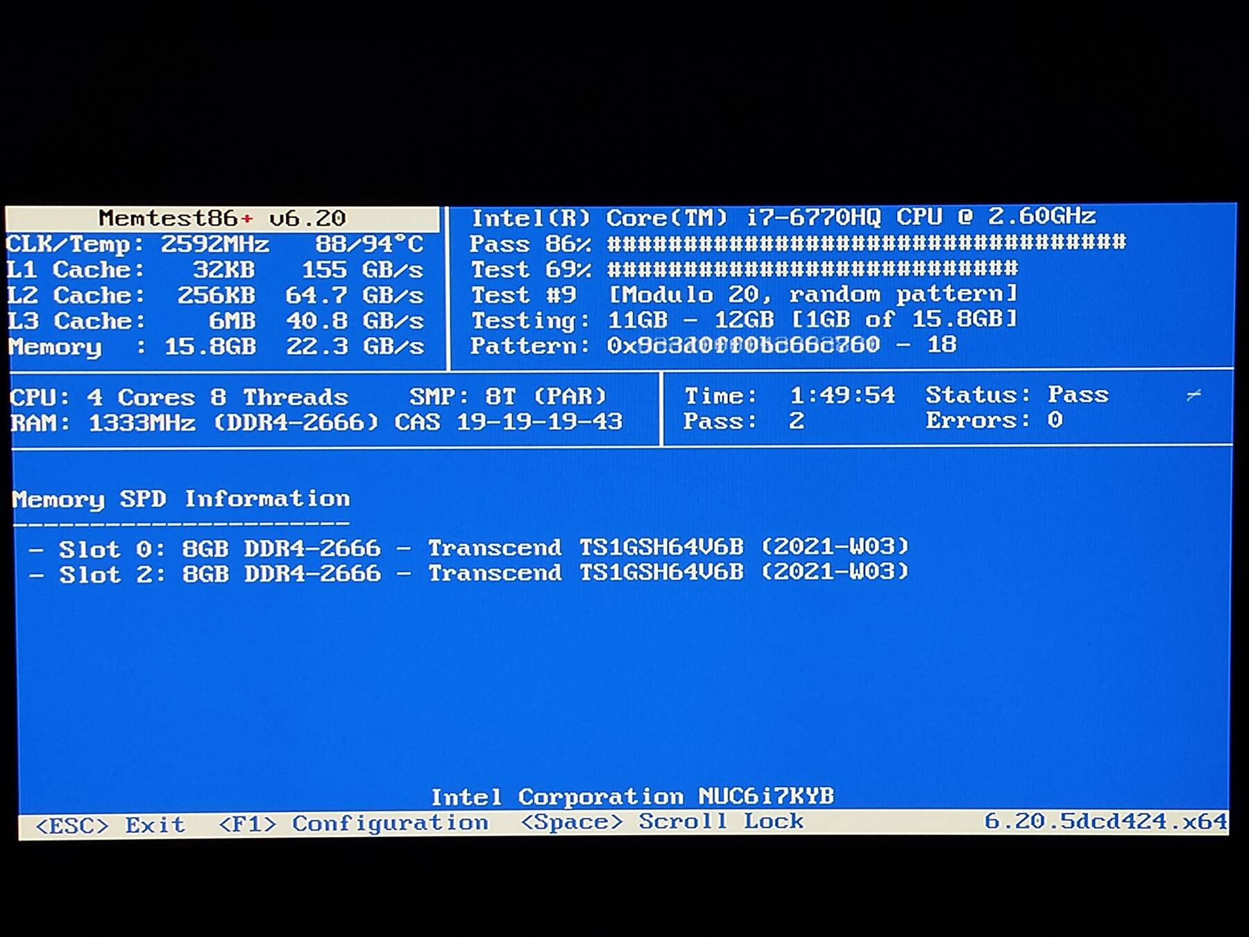
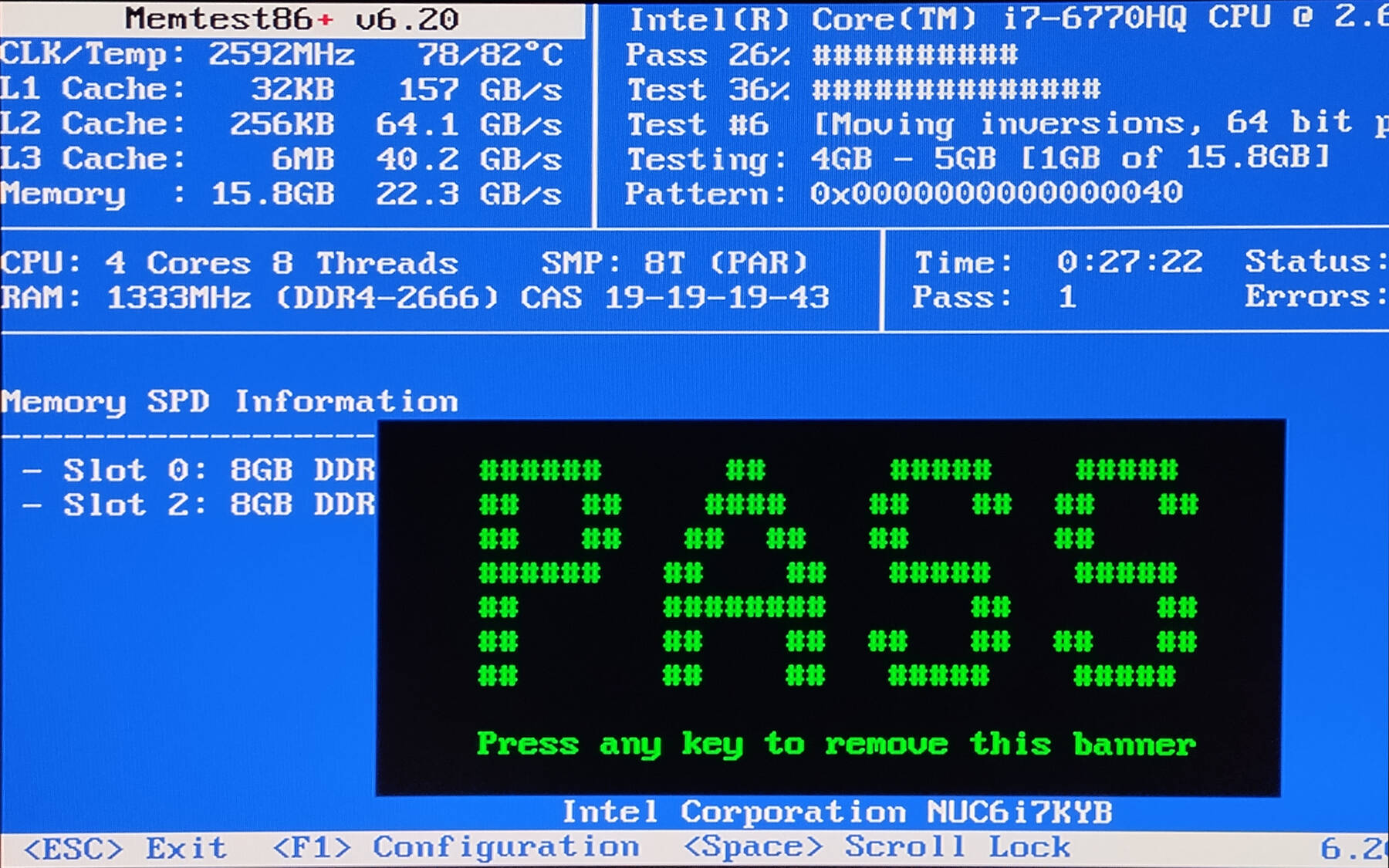
I ran Memtest86+ for 8 passes without issue. CPU stayed pretty hot, around 90°C with a peak of 97°C.
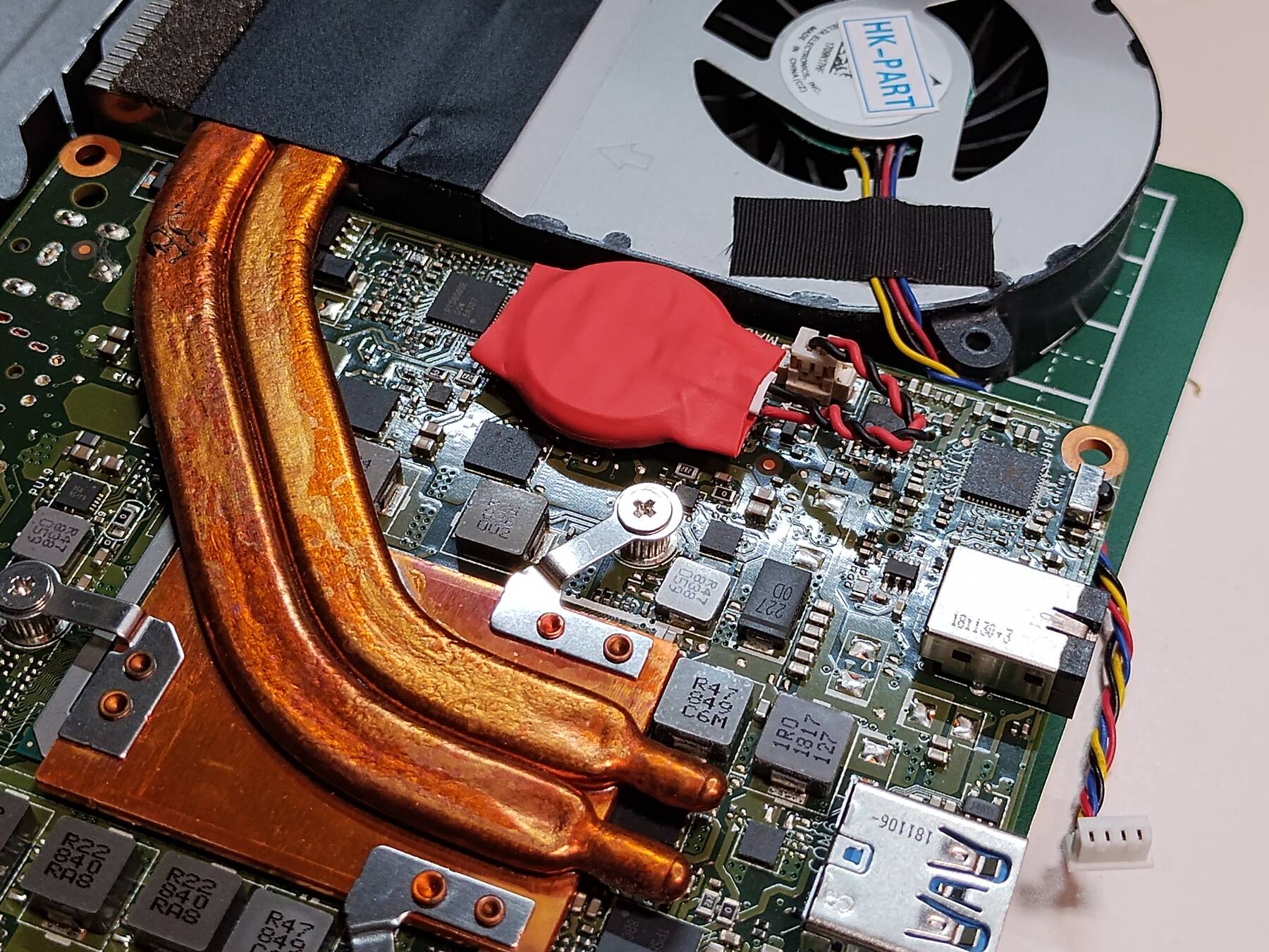
The CMOS battery is dead in this unit. It keeps forgetting the date, fan settings, and powers on whenever I reconnect power. I guess it is about 8 years old, but it still feels much too new to have to worry about dead batteries.
While having a look inside I ripped the tabs off the old battery. Then I welded them to a new battery, and covered it with some bits of heatshrink. A bit of double stick foam tape secures it.
Cooling mod - Planning
The fan is noisy. It needs some help if I'm going to encode video 2 feet away from where I'm recording.
- Other solutions
First mod I saw was just a passive heatsink: Skull Canyon NUC Cooling Mod
Then I saw some using larger heatsinks mounted to the steel chassis.
- uplink777 Noctua NH-L9X65 SE-AM4
- Intel NUC NUC6i7KYK w/Noctua cooling mod (Skull Canyon) (for sale post)
- skull canyon noctua cooling mod - FatherofaMonster (photos in comments)
- My idea
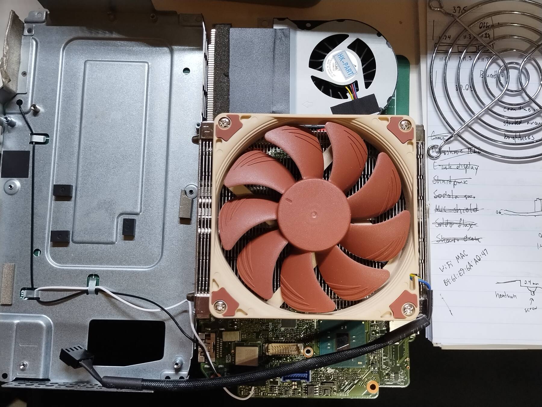
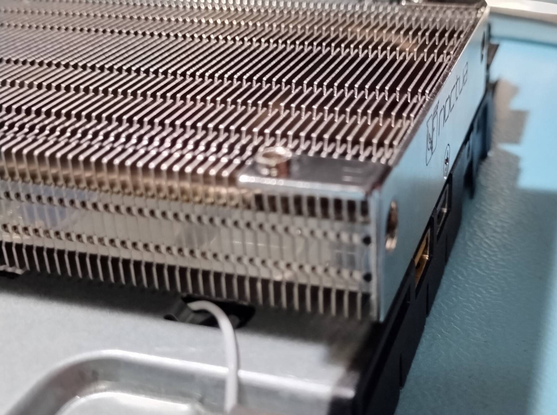
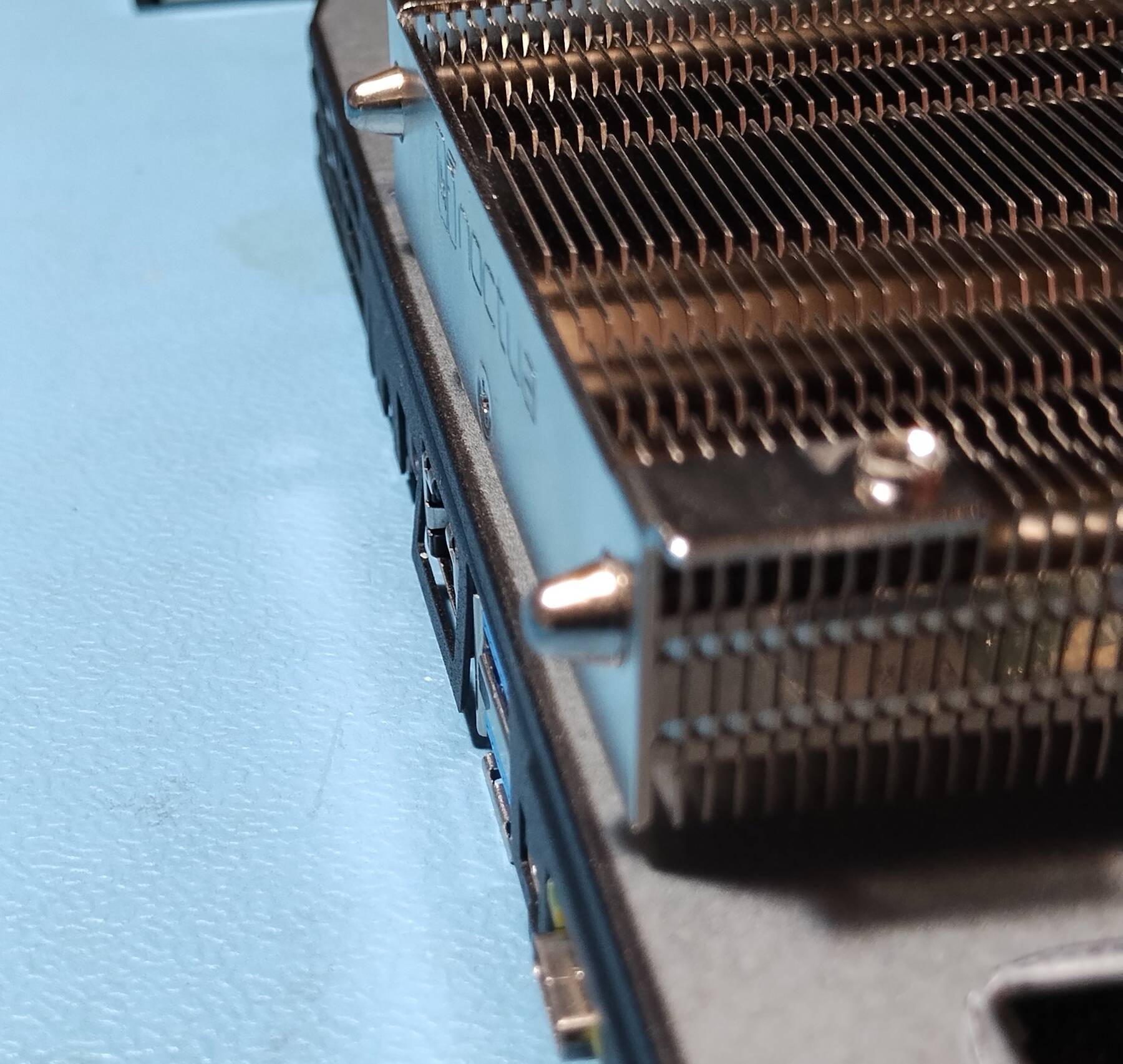
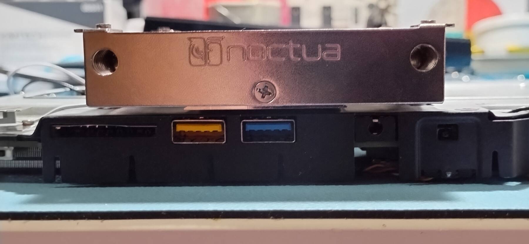
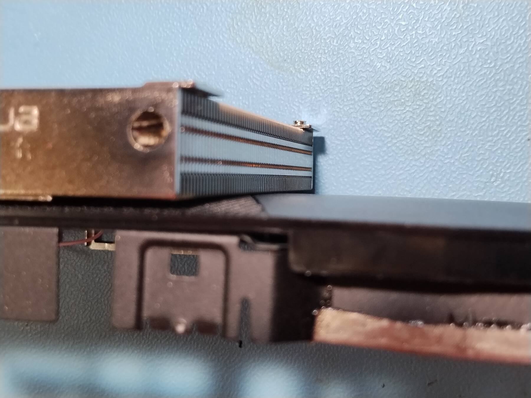
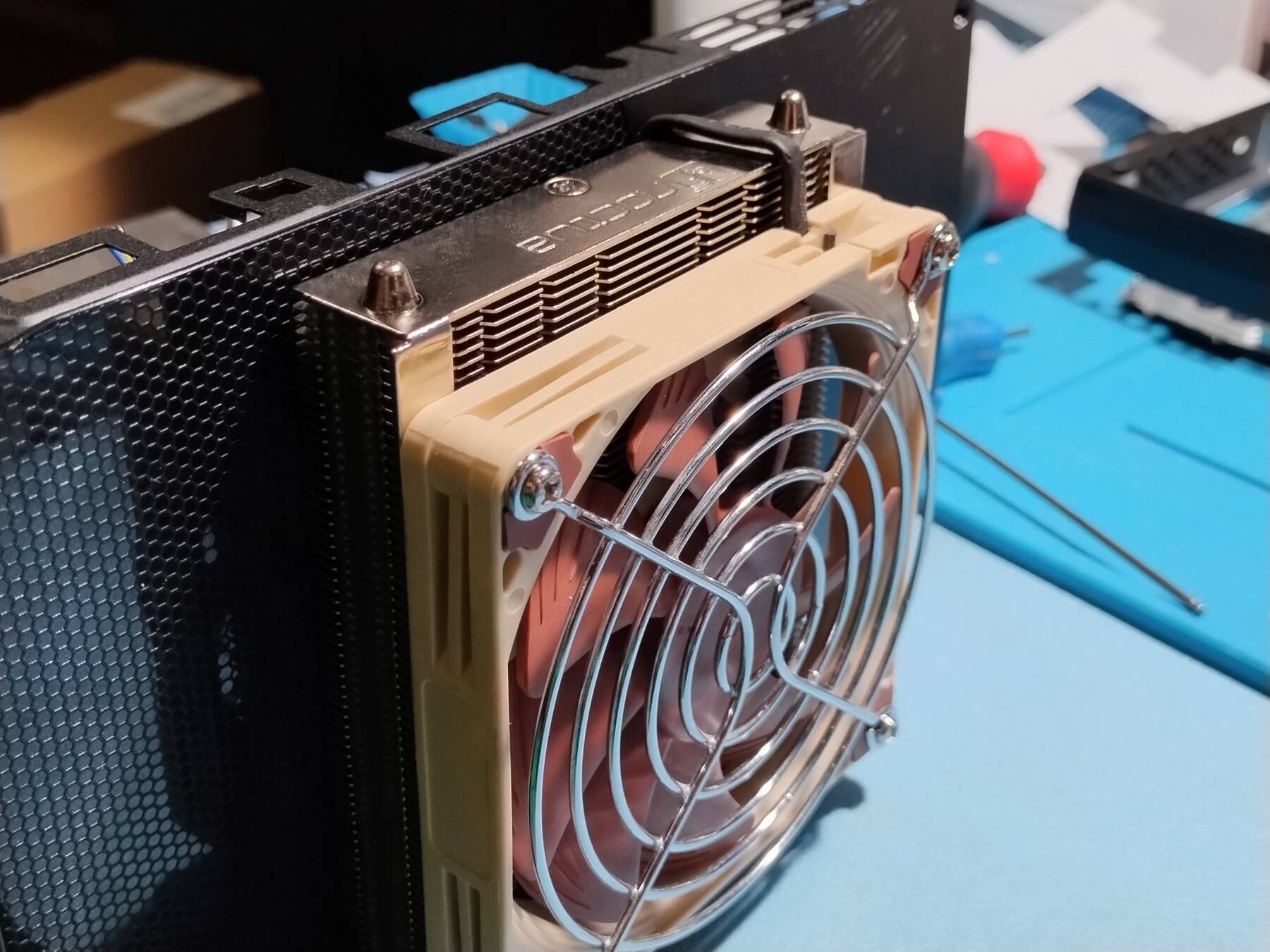
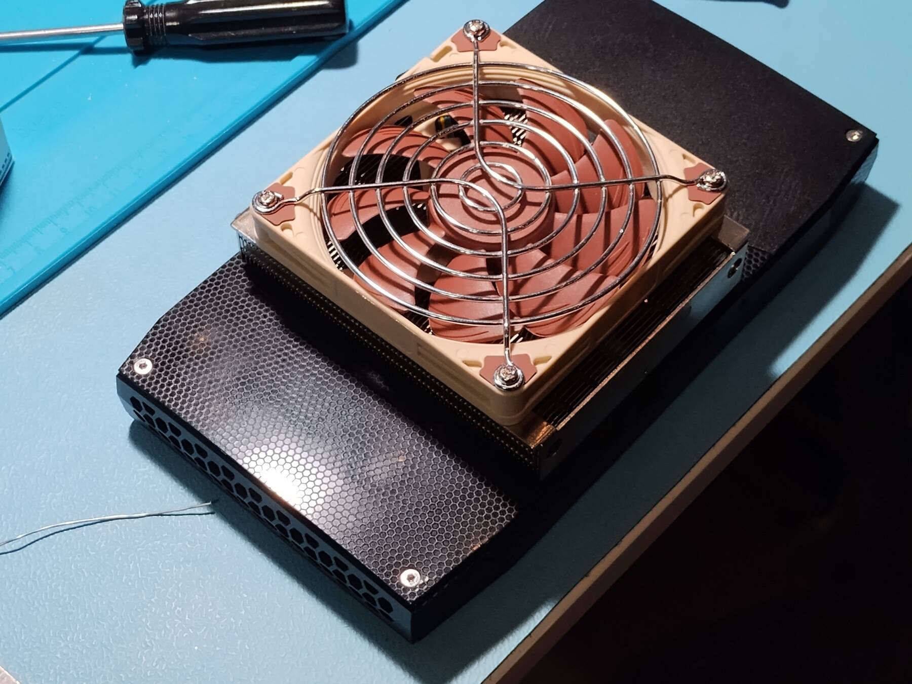
I have a Noctua NH-L9a. This is a low-profile AM4 heatsink. It is rather hefty, but a pretty good size for the NUC.
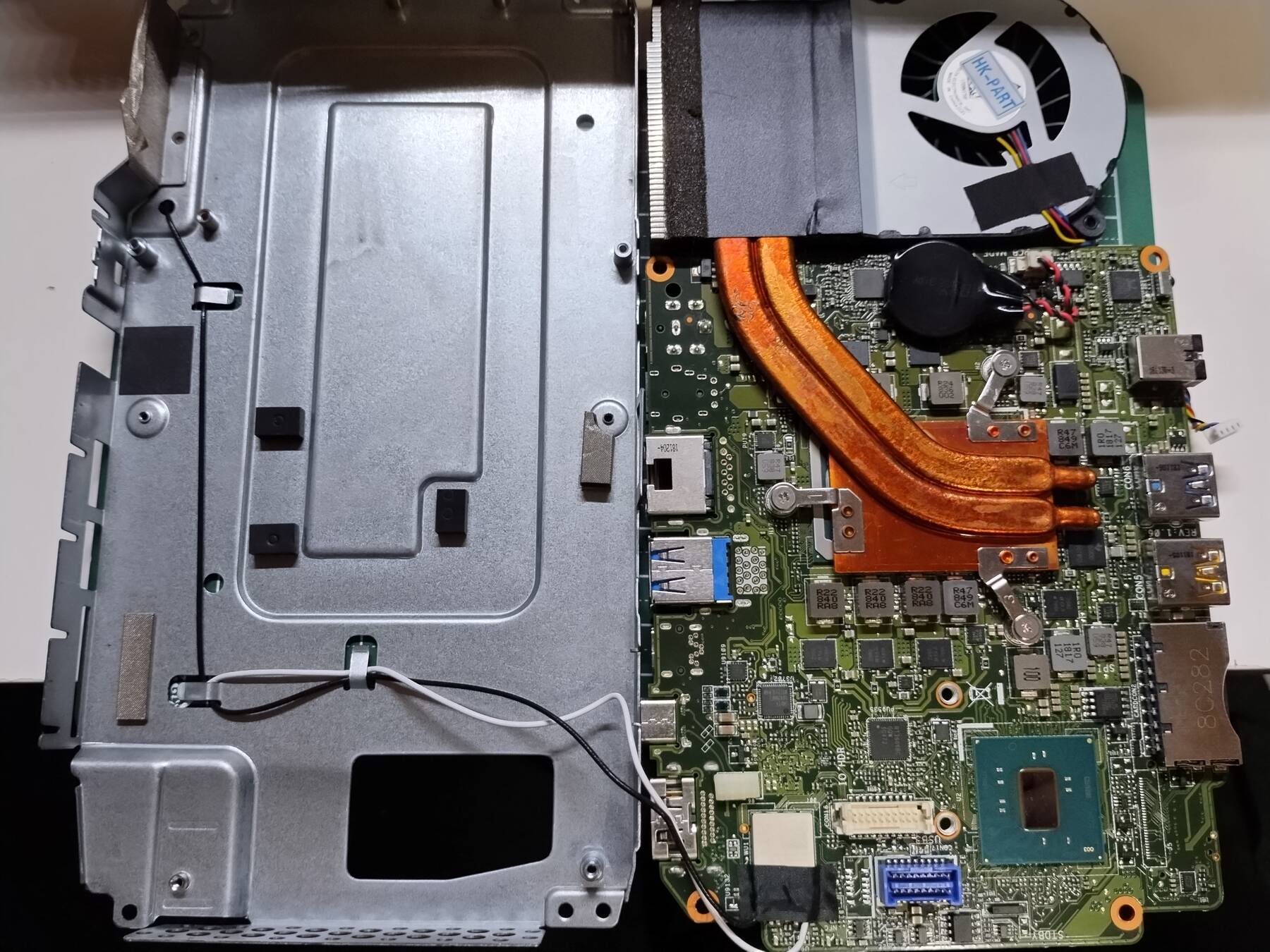
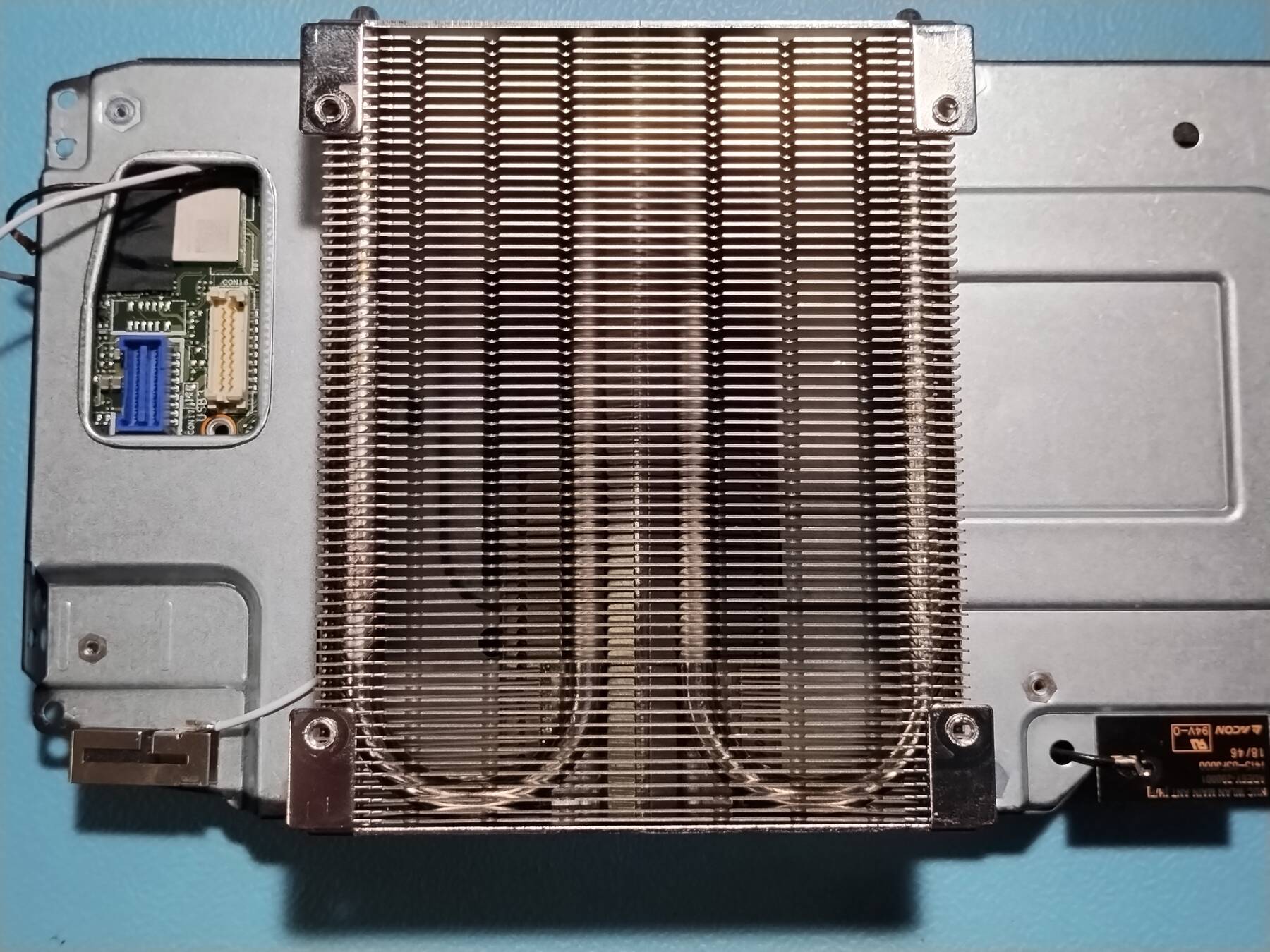
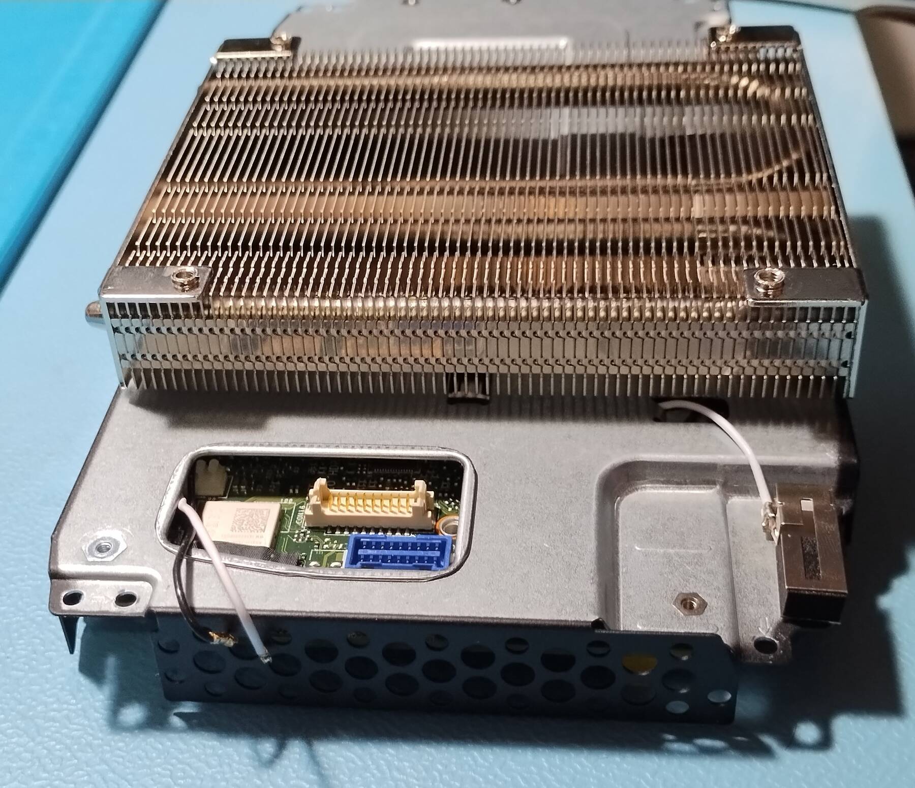
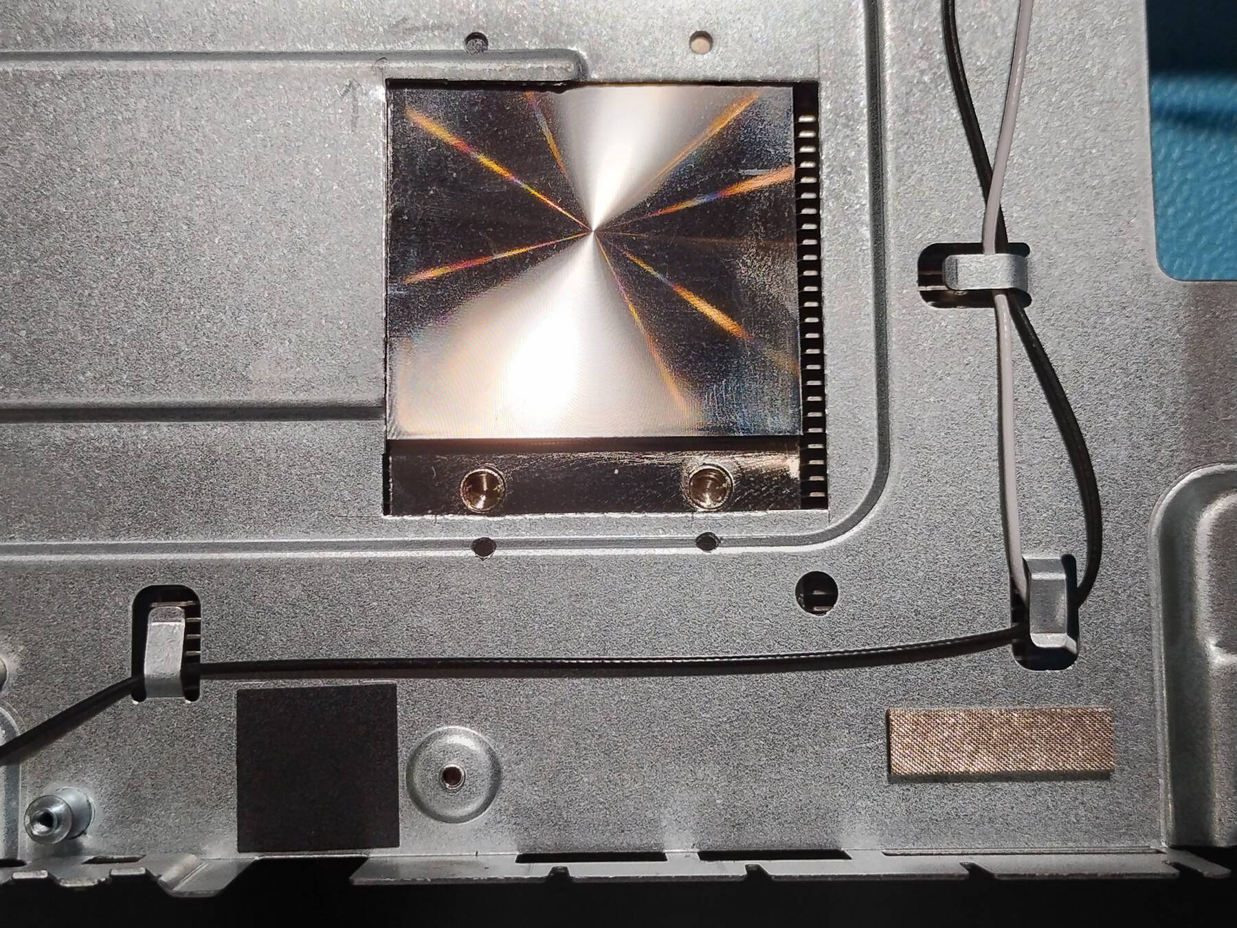
I'm going to cut a square hole, and drill 4 mounting holes in the chassis. Then remove the heatsink mounting clips, and attach it directly to the chassis with 4 screws from the other side. It will rest on top of the heatpipes.
The stock heatsink, and blower stay in place. The blower provides airflow for rest of the components, and mounting directly to the CPU would complicate things.
Compared to the other solutions it is fairly low profile, and a bit simpler to mount. The downside is that removing the heatsink requires complete disassembly.
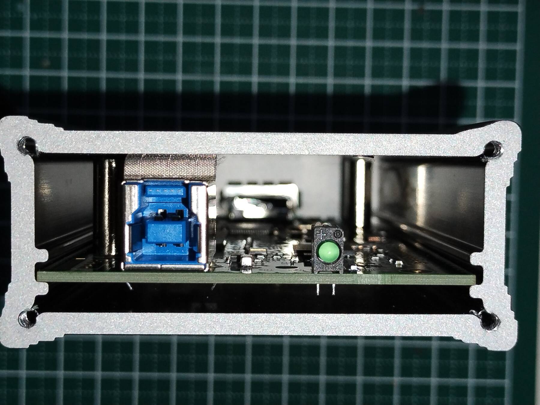
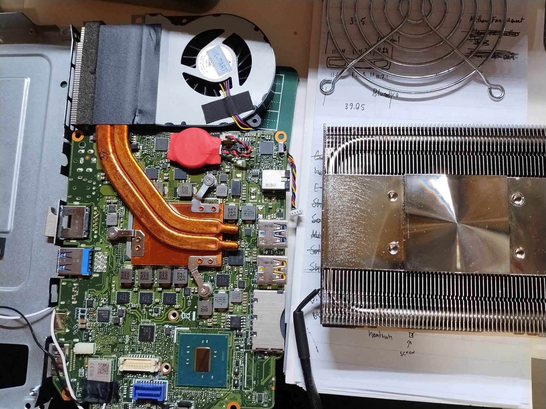
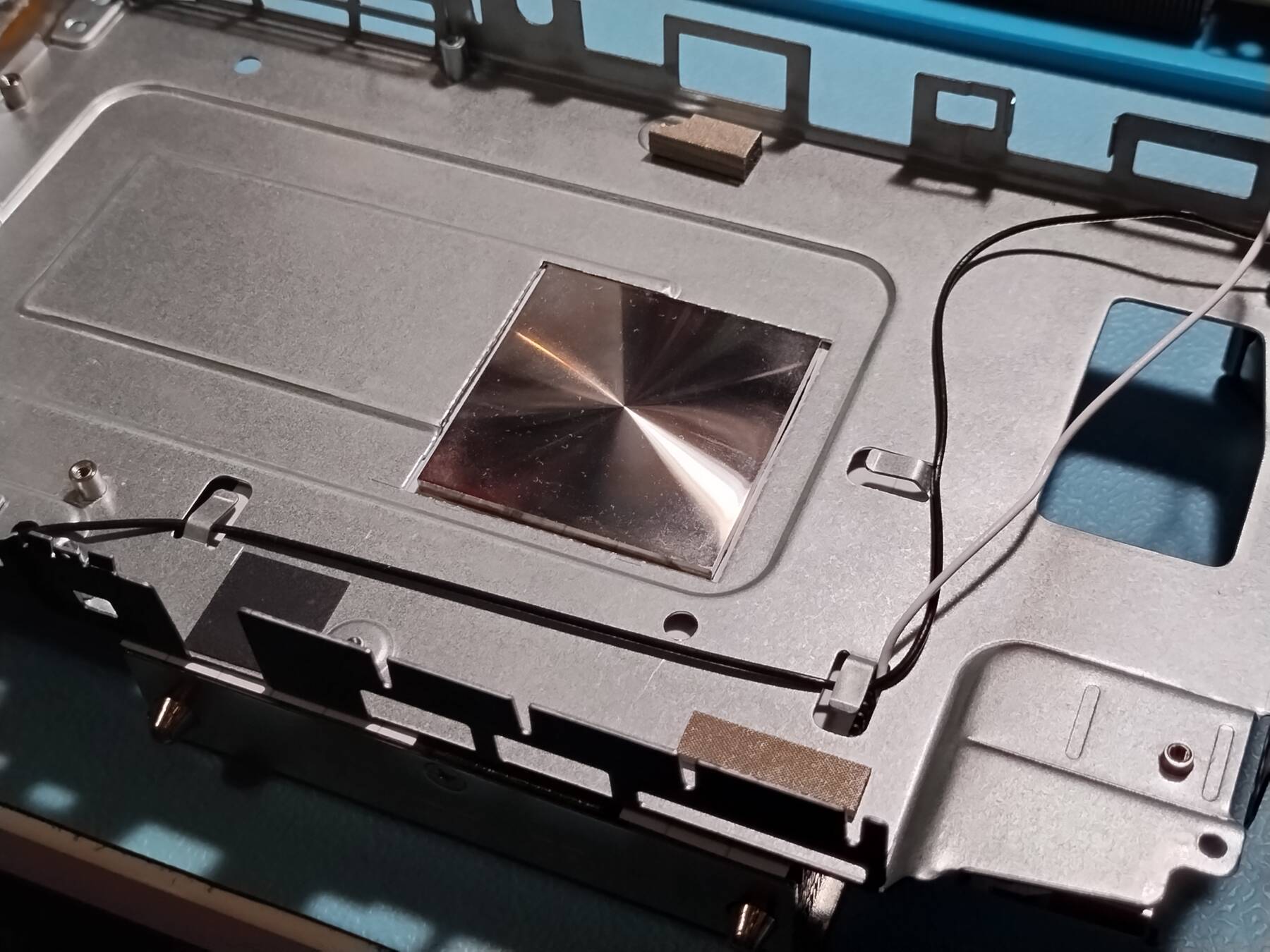
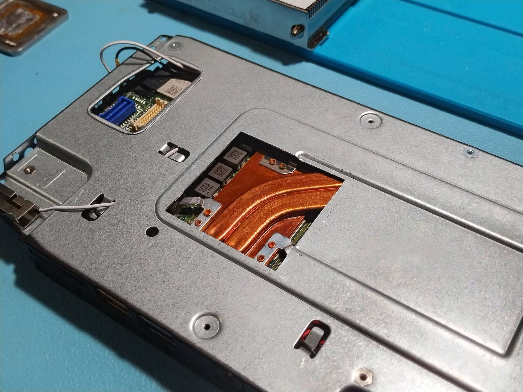
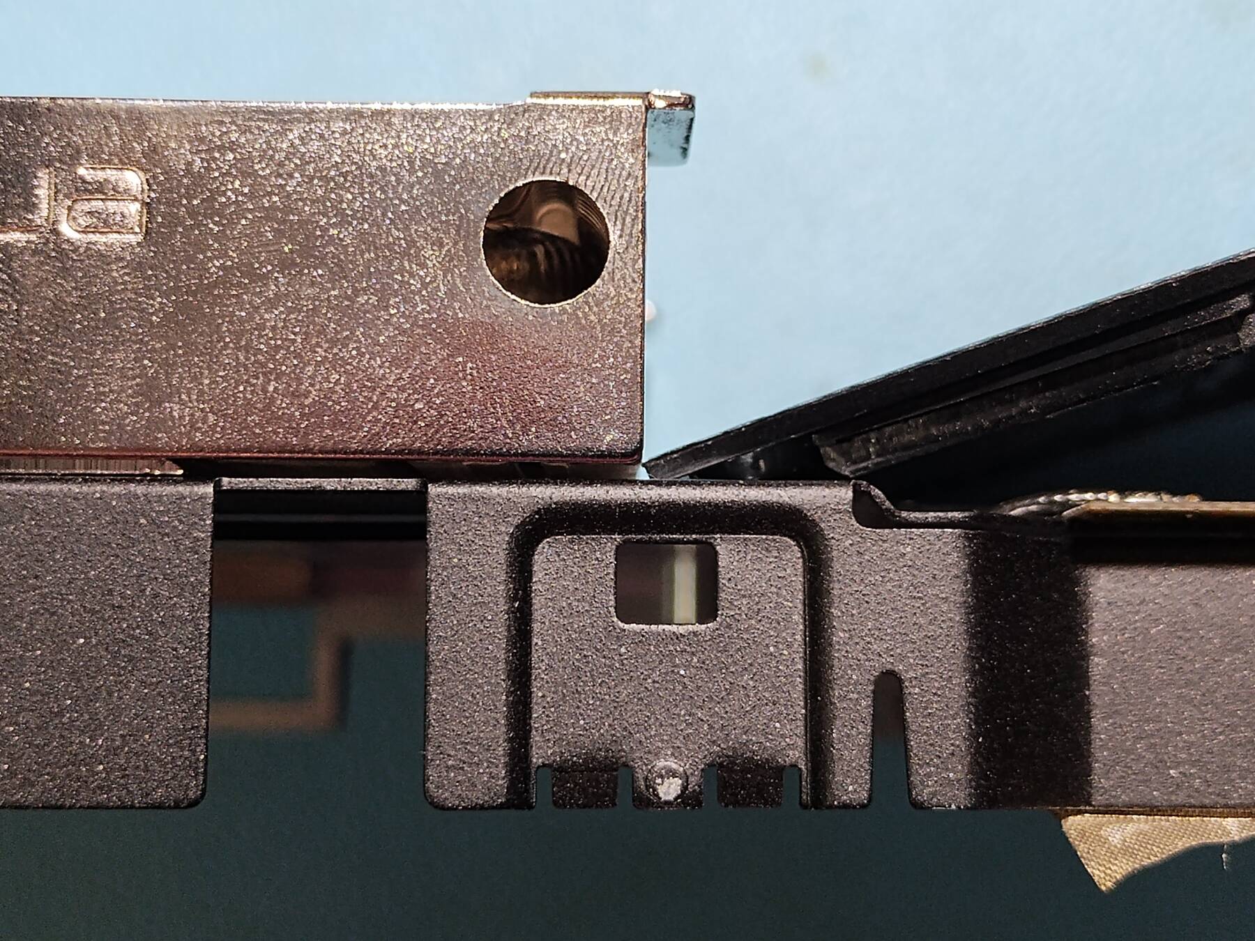
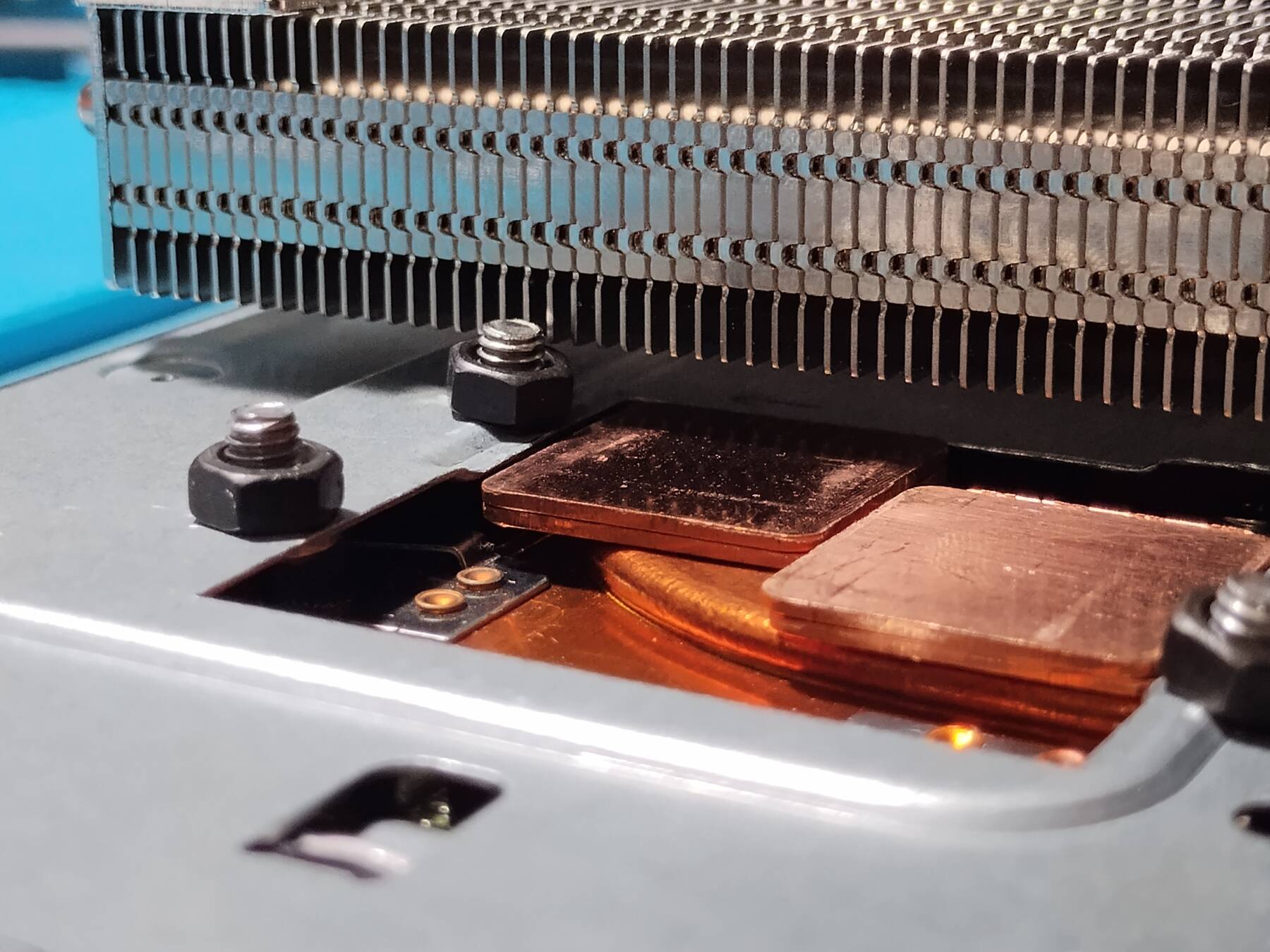
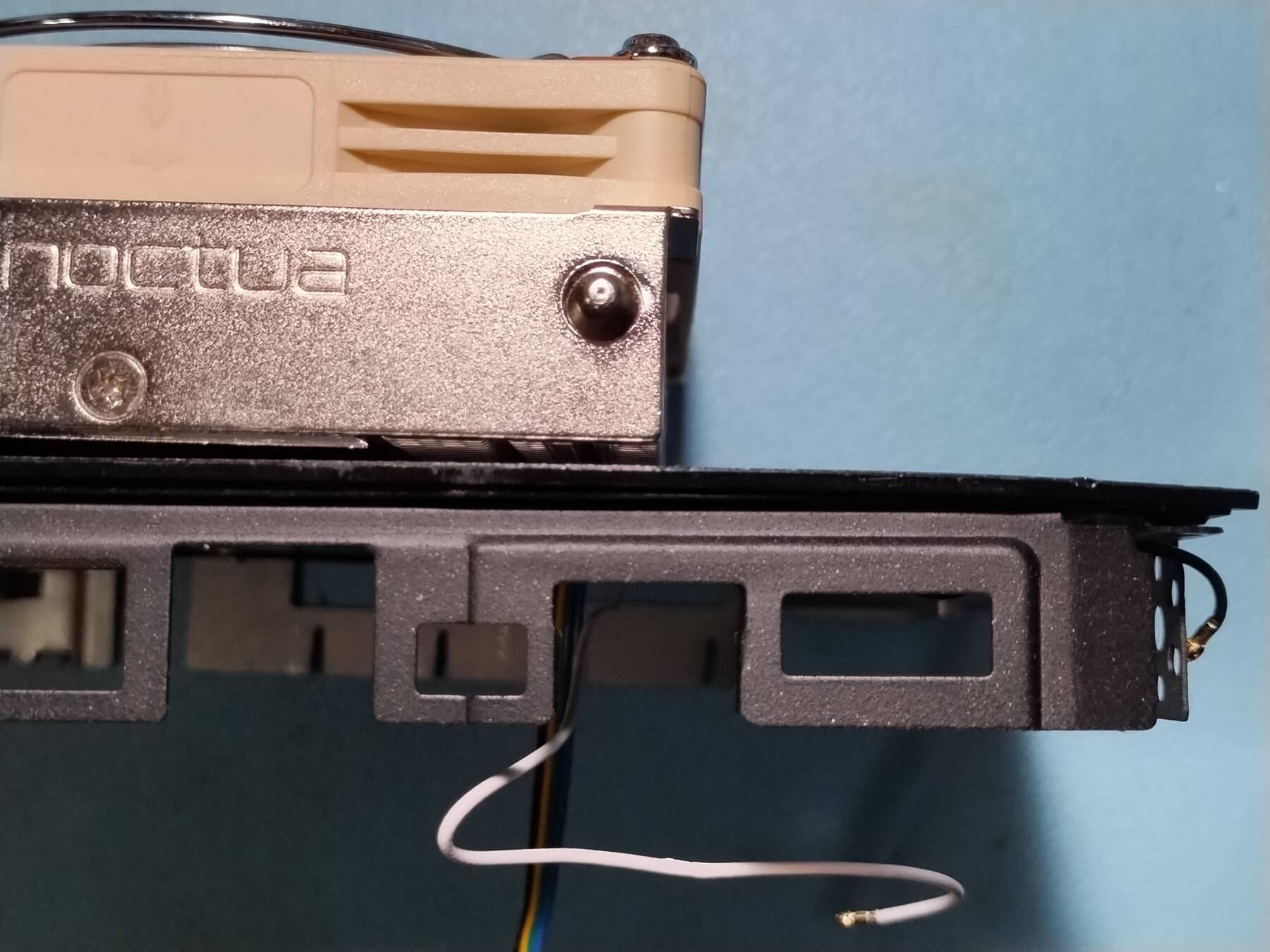
- Lets measure some things
- chassis metal is 0.6mm thick.
- difference between raised and lowered sections of sheet metal is 1mm.
- stand-offs are 6.15mm.
- PCB to top of heat pipes is 5.7mm
That's about 0.45mm from top of heat pipes to metal plate
Definitely could add a thermal pad along a lot of the heatpipe.
The heatsink has about a 2.4mm step. Accounting for all my above measurements it only needs to be 2.05mm. So that is 0.35mm more material than I need. Plus taking into account some thermal pads.
I expect the steel chassis will have some flex to it, but I'm not sure it is enough. I may need to shim the heatsink away slightly.

Figure 1: Rough diagram of CPU, Heat pipe, Chassis, Heatsink stack - Poking about conclusions
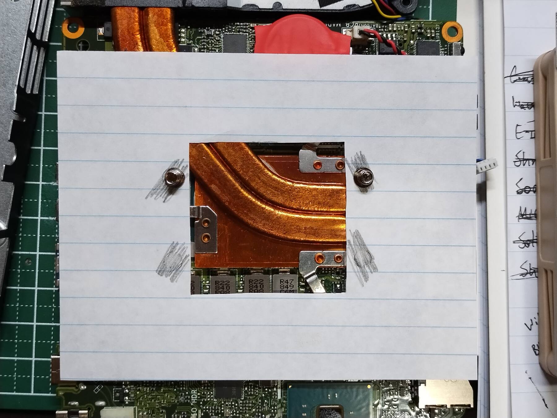
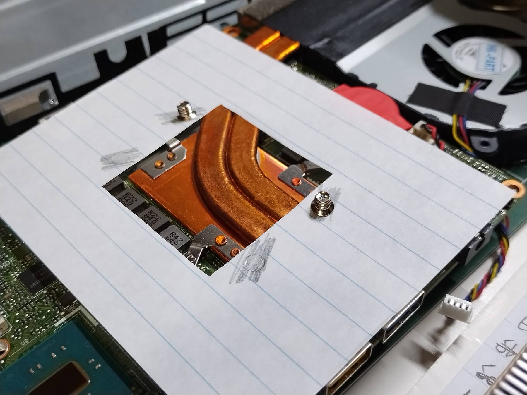
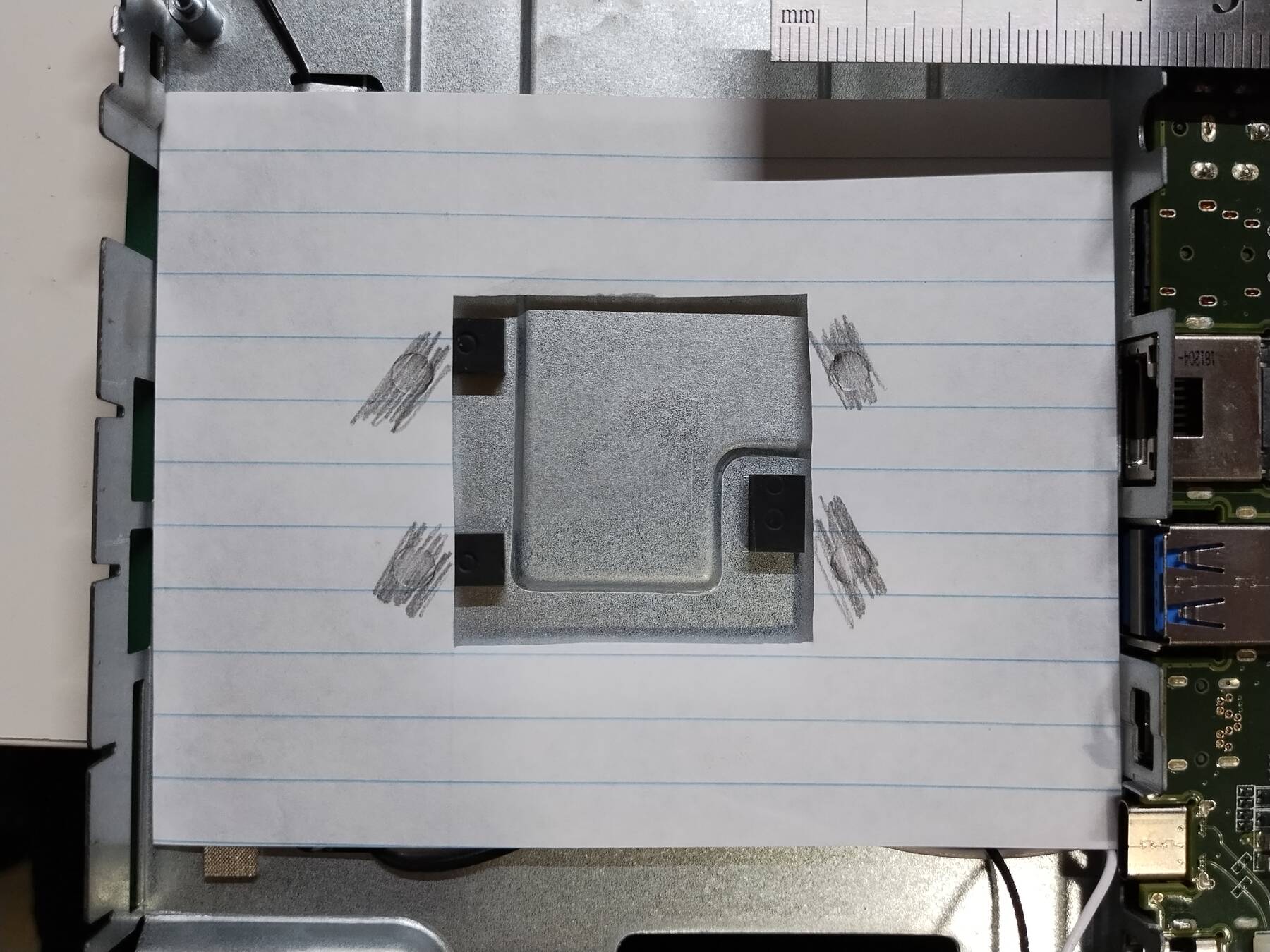
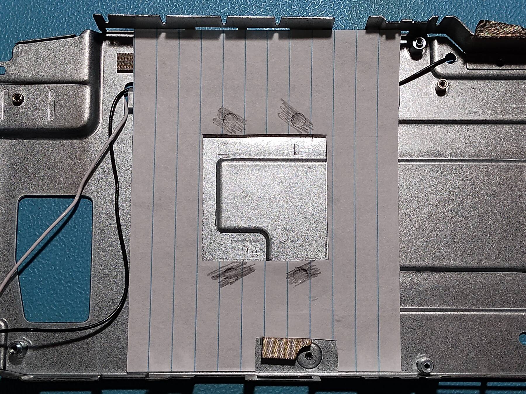
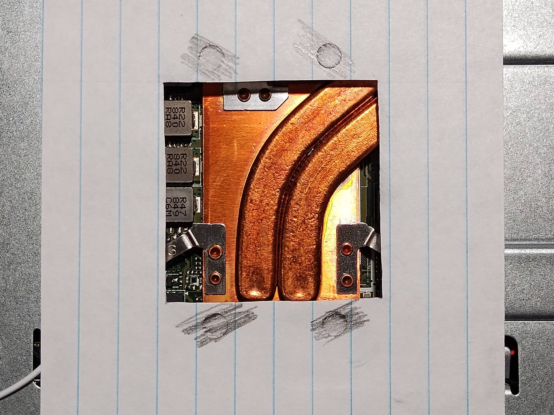
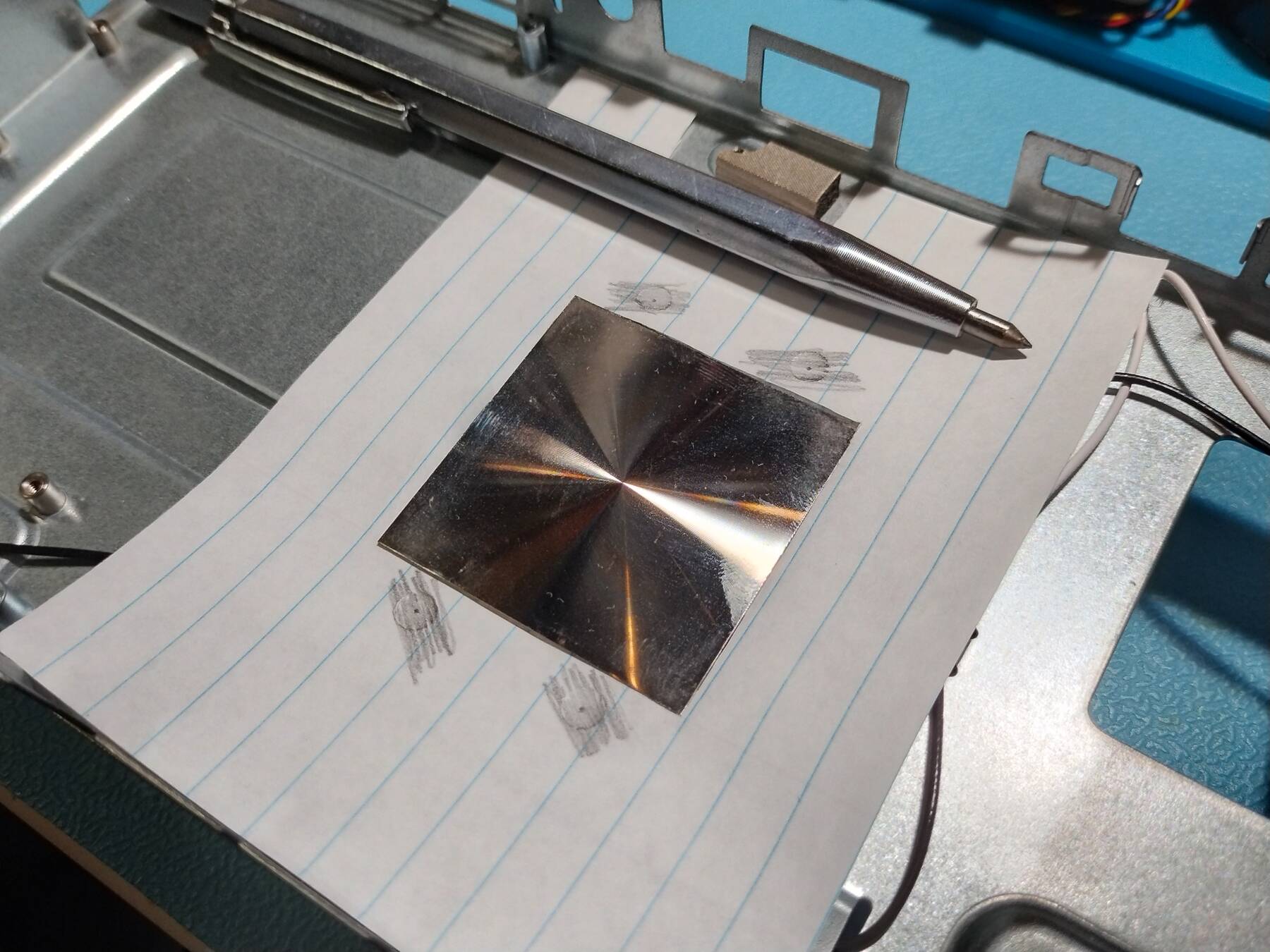
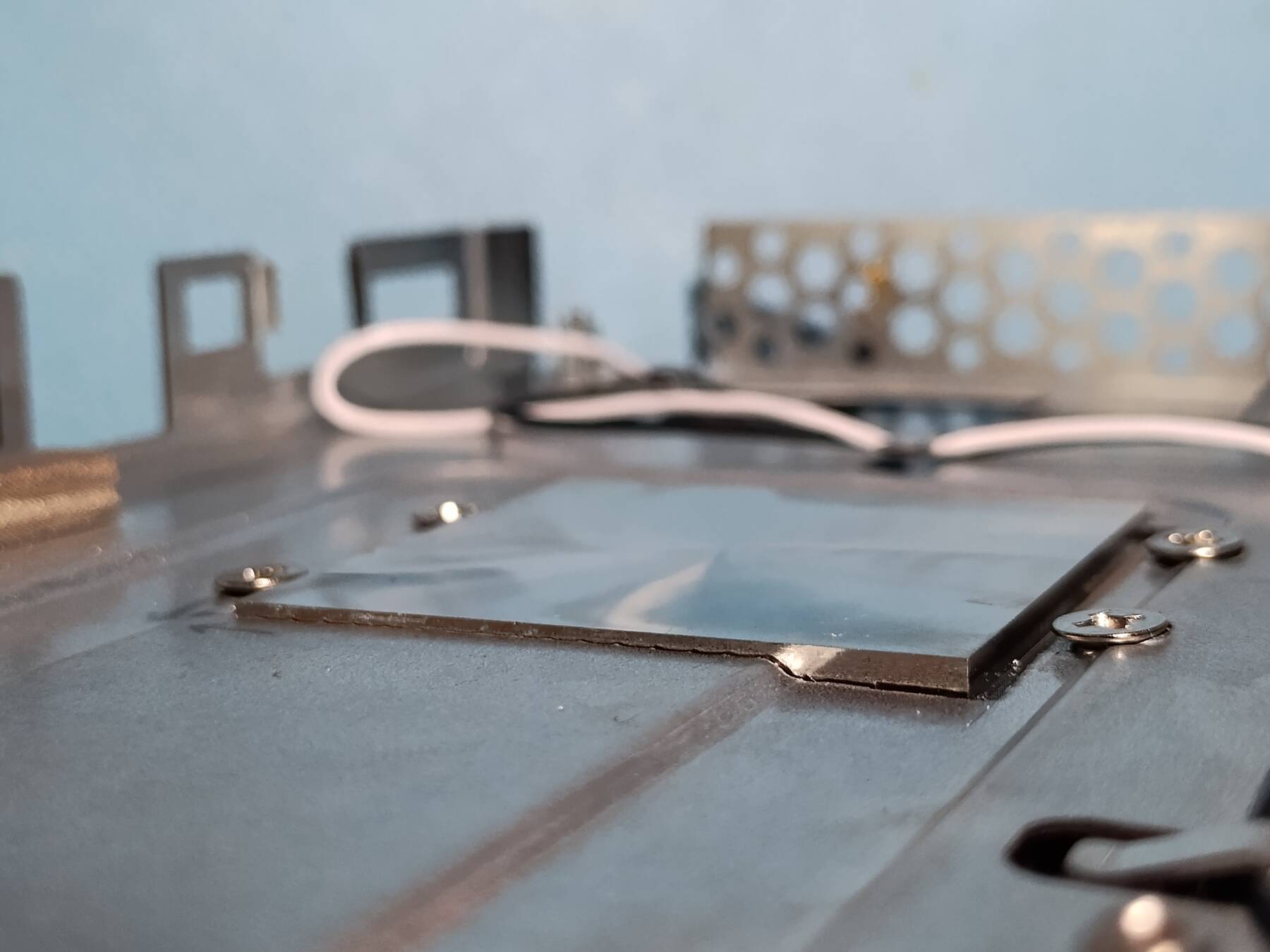
I cut out a paper template of the heatsink profile, and marked the screw holes.
The heatsink has to be shifted slightly to the side to give good clearance for the screw heads.
Heat pipes are a bit uneven.
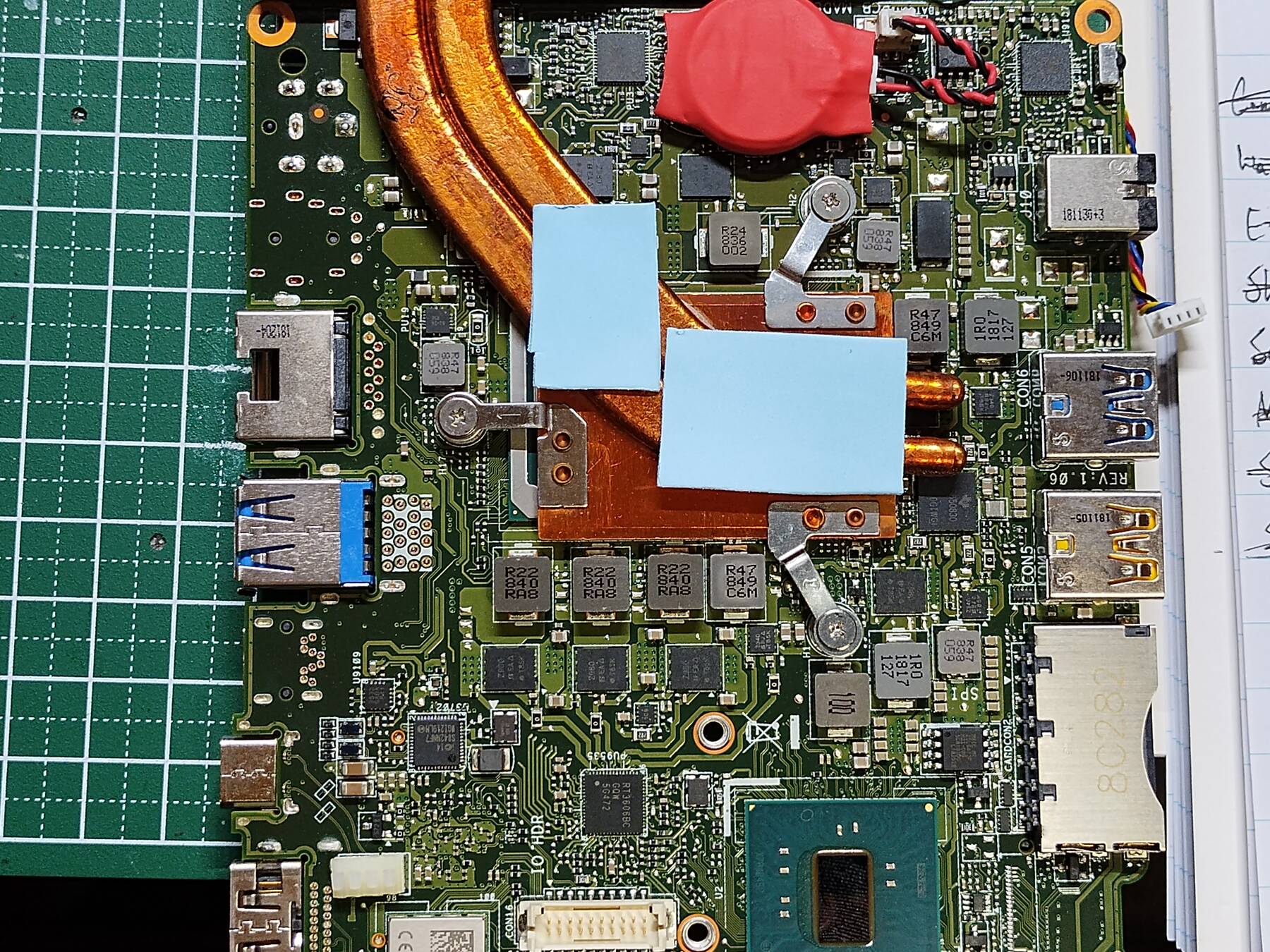
- What about just a couple thermal pads?
I added two thermal pads where they seemed likely to contact the metal chassis. I reassembled everything, and ran Memtest86+ again. After the first pass the CPU had a maximum of 93°C. I let it soak for about 3 passes, and the maximum temp ended up being 94°C. Less than the 97°C I saw previously, but not very significant.
- The plan at this point
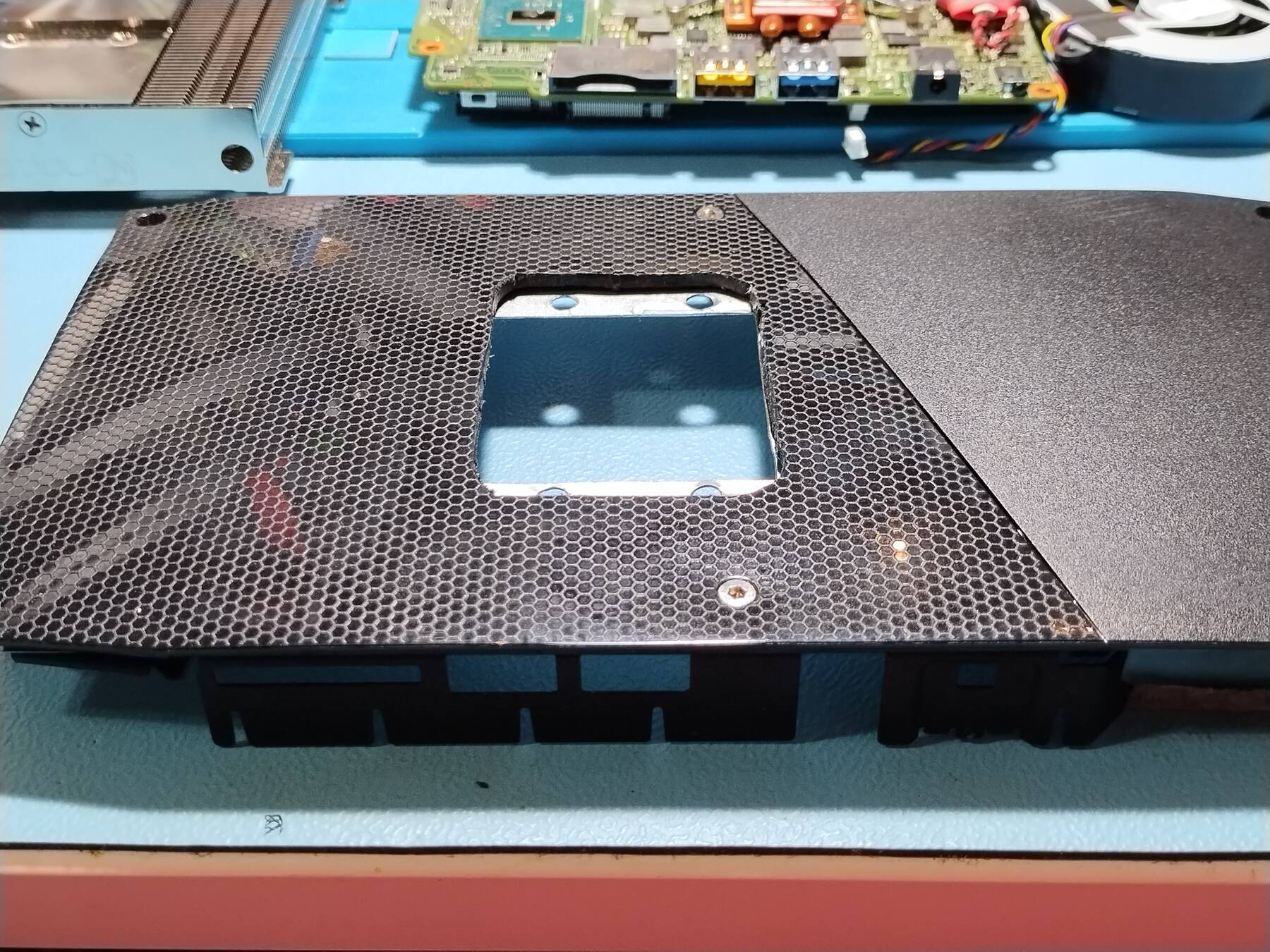
- Use my template to best approximate where to cut the square hole
- Add 1mm clearance, and cut out a square in the metal chassis with a nibbler
- drill 4 holes
- mount the heatsink to the chassis
- pull the stock heatsink, and re-paste it
- test fit to see how much the chassis can flex
- add spacers if necessary (might need longer screws)
- assemble with thermal pads
- test with and without fan
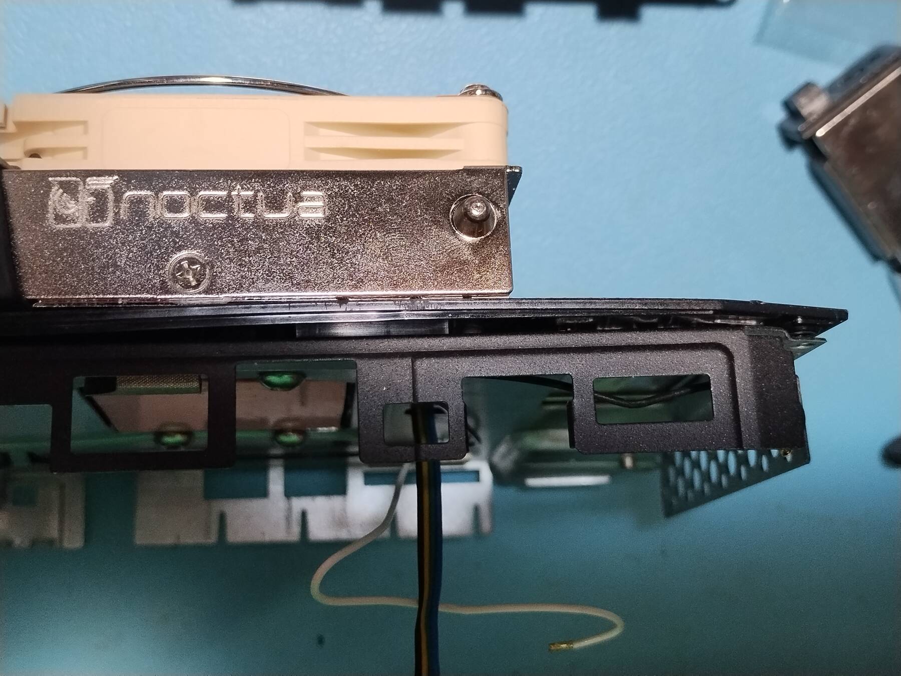
Cooling mod - Heatsink mount and fitting
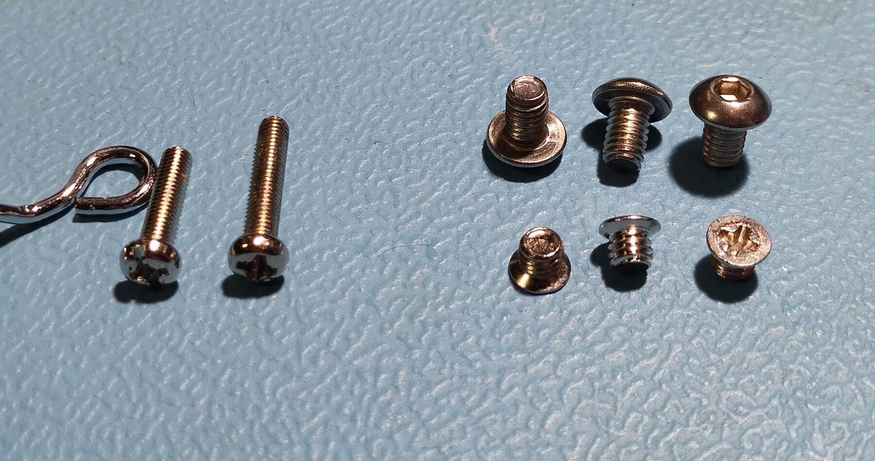
First step was finding some new screws for the heatsink. The M3 fan screws need to be extended to account for the grill. The M4 mounting screws need to be longer to accomodate adding spacers. I settled on some button head M4 x 6mm screws for the heatsink, and despite the larger heads they should still clear the heatpipes.
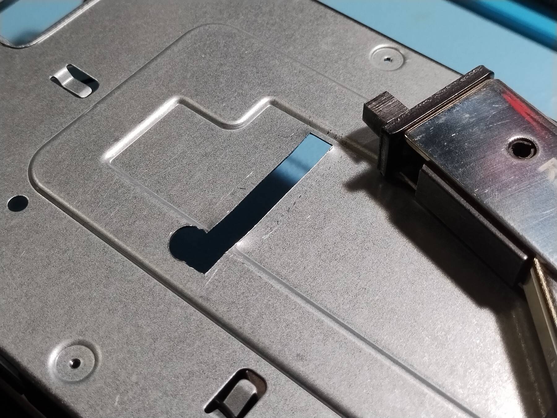
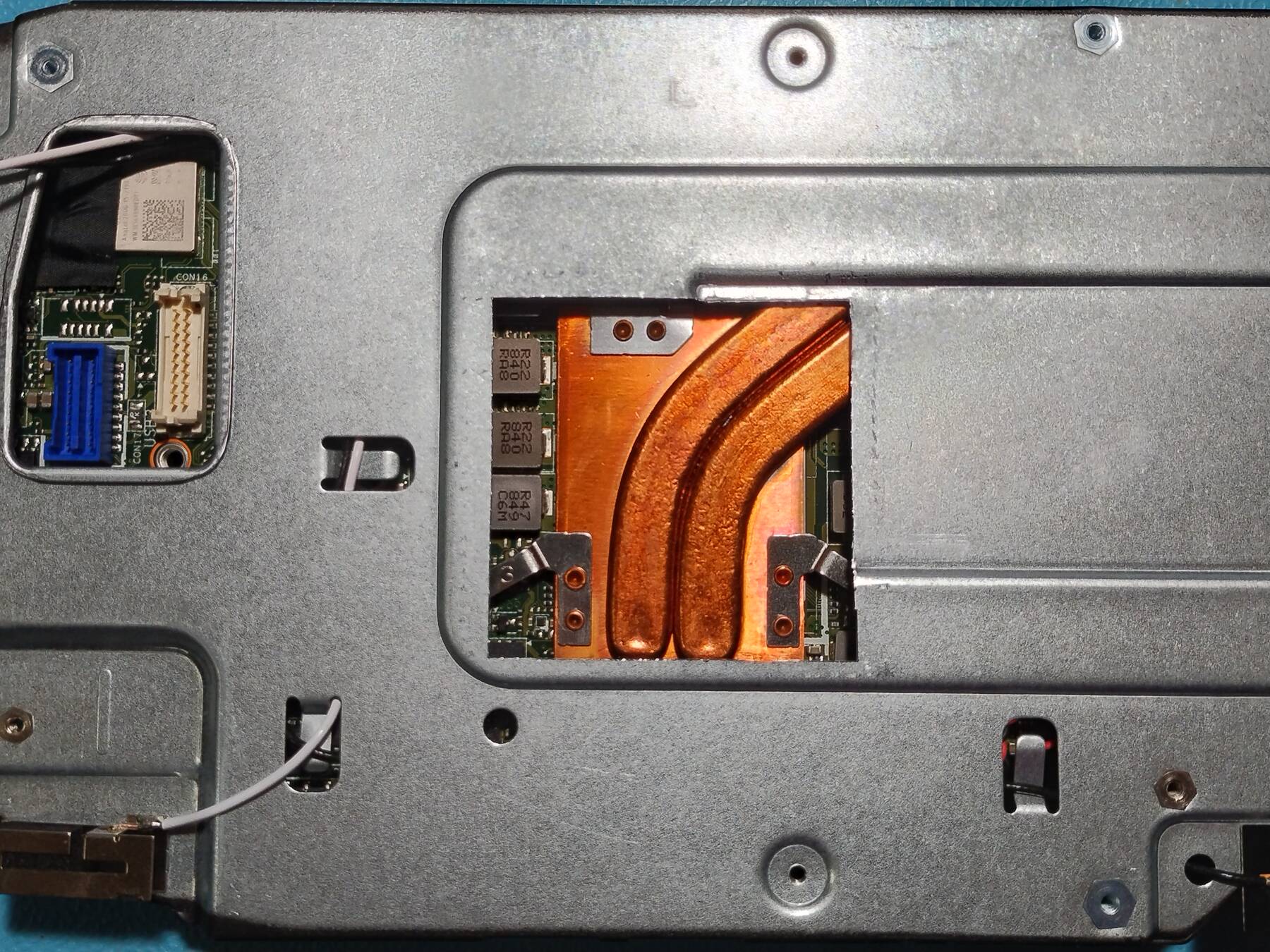
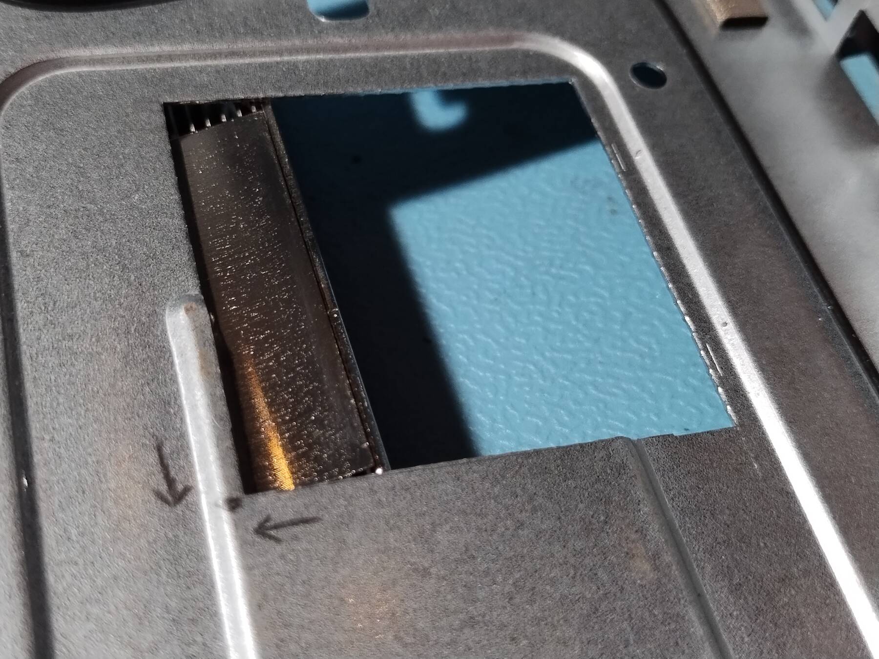
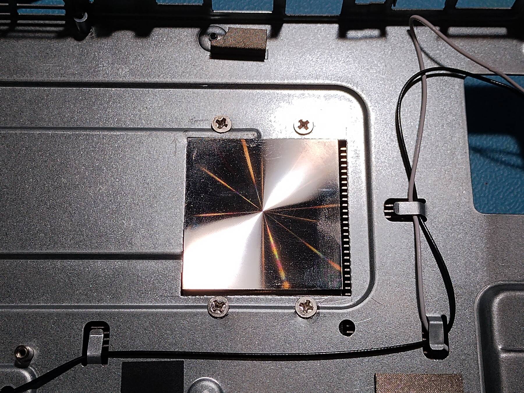
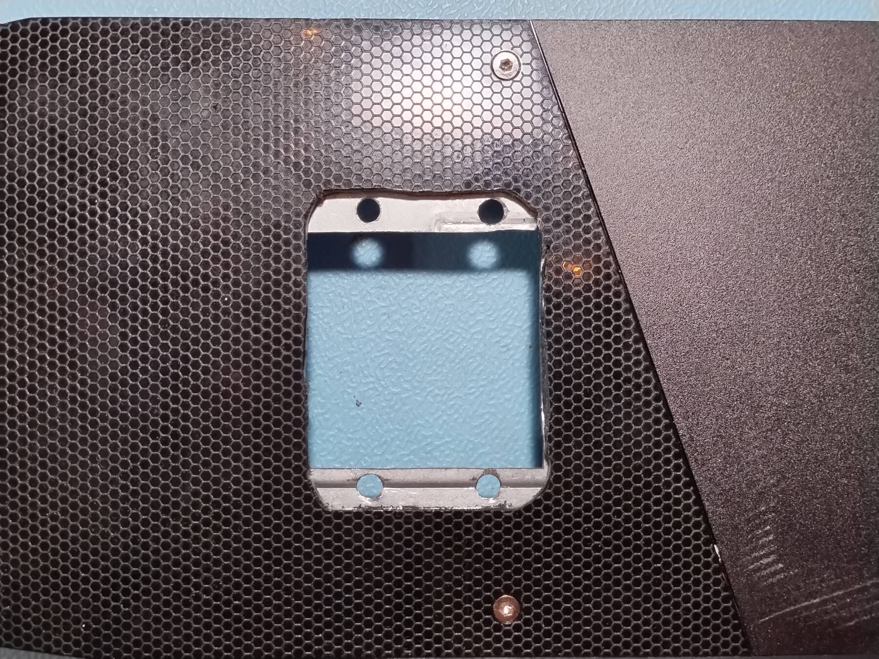
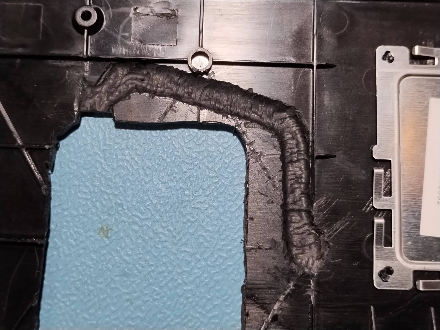
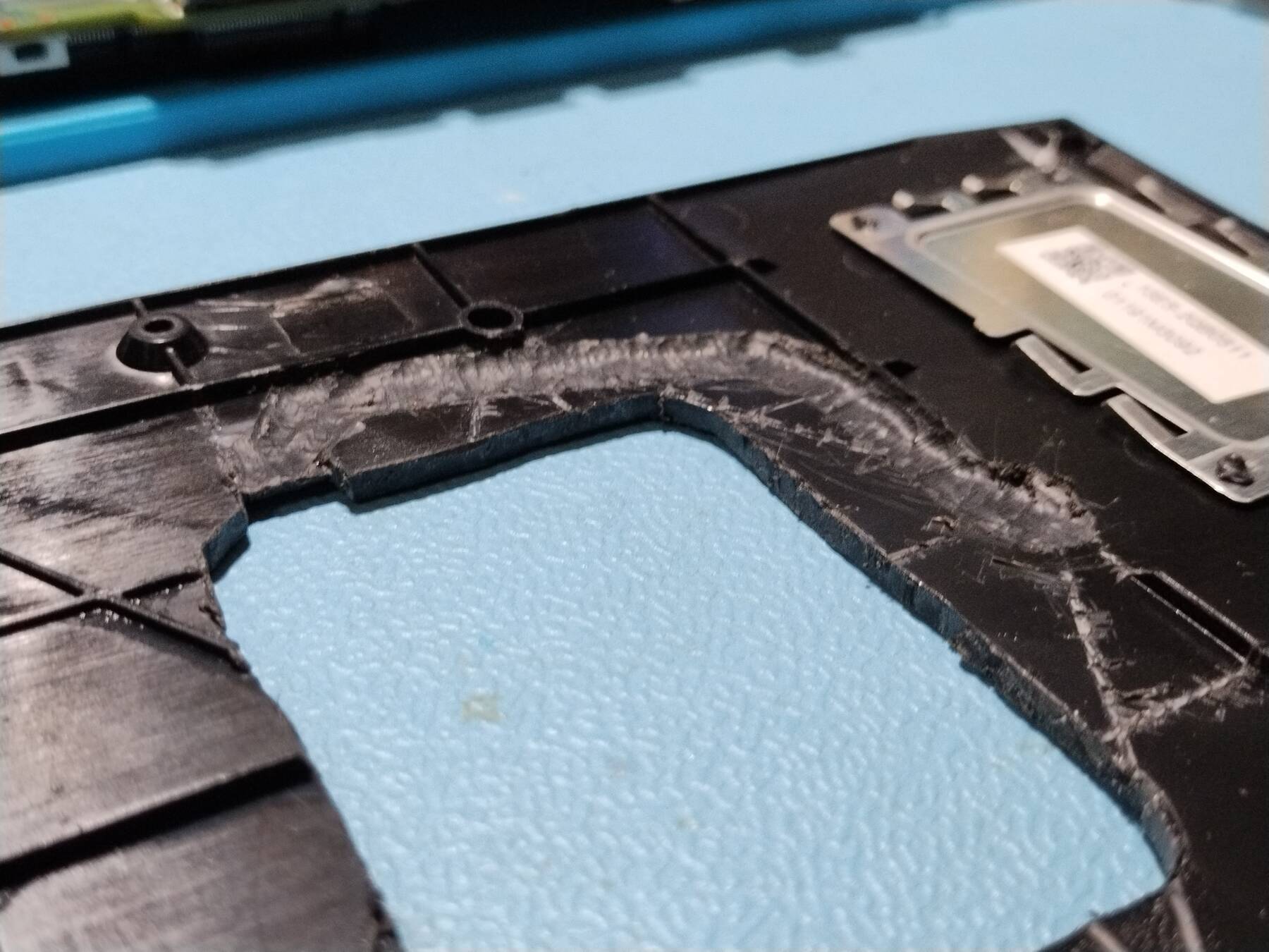
- Cutting up the chassis
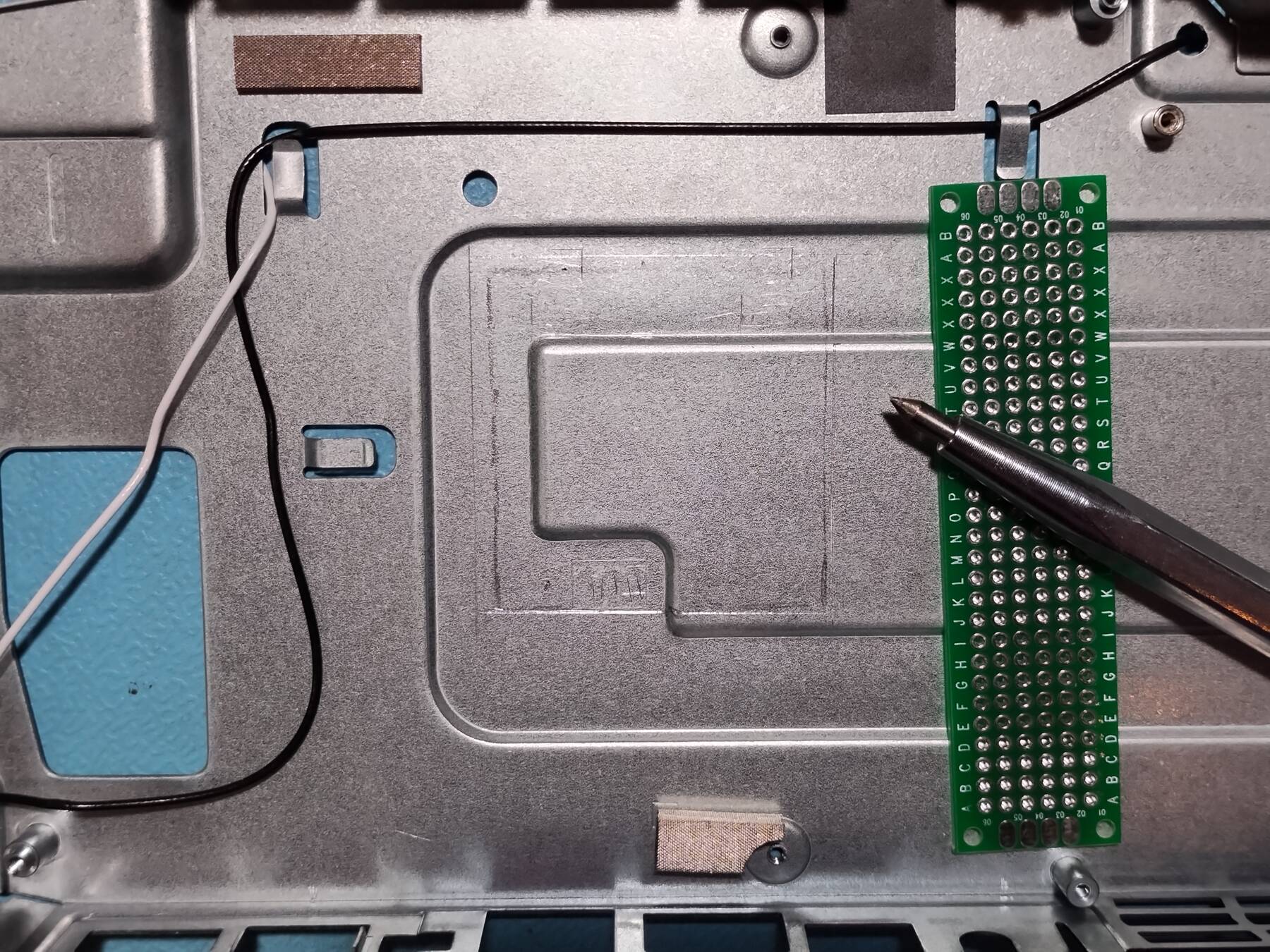
Next I positioned my paper template, and traced the square onto the chassis. Then I re-drew it slightly larger with a straight edge, and scribe.
Nibbling across the 3D sheet metal was a little messy. I used a bit of metal and a hammer to straighten things back out afterwards.
Some test fitting was done. I think I might get away without having to shim the heatsink out.
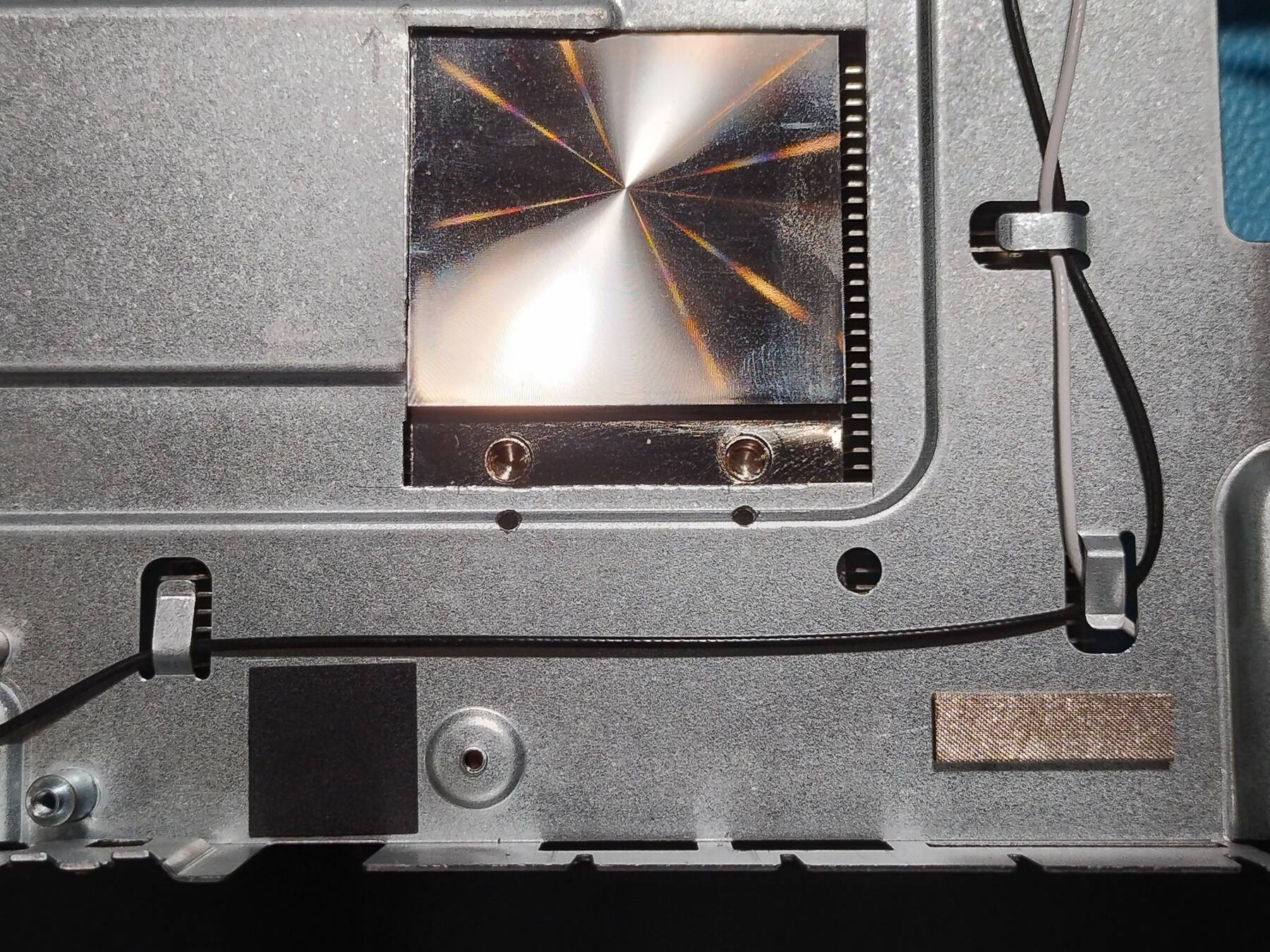
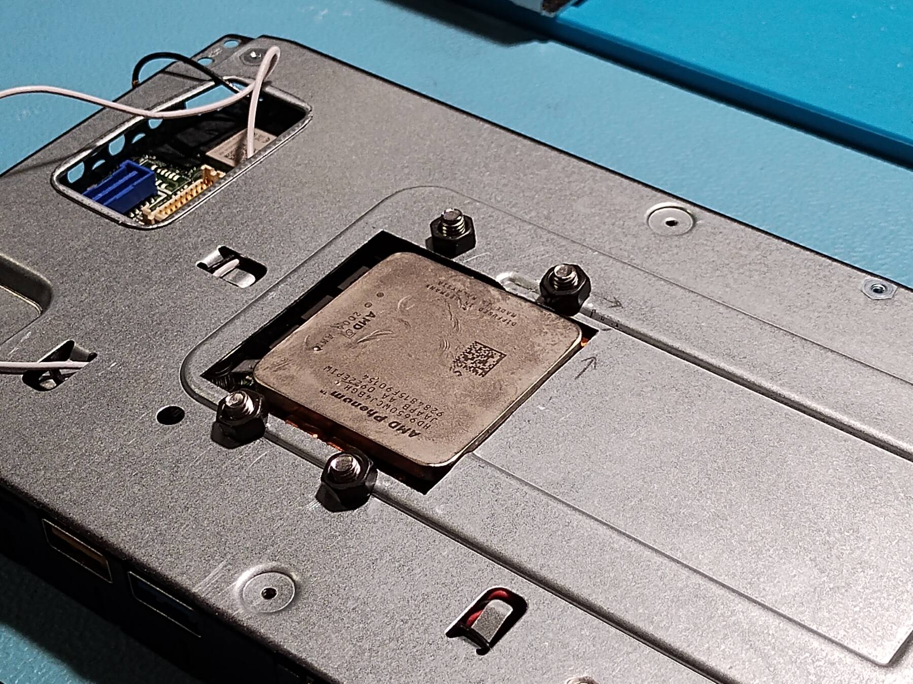
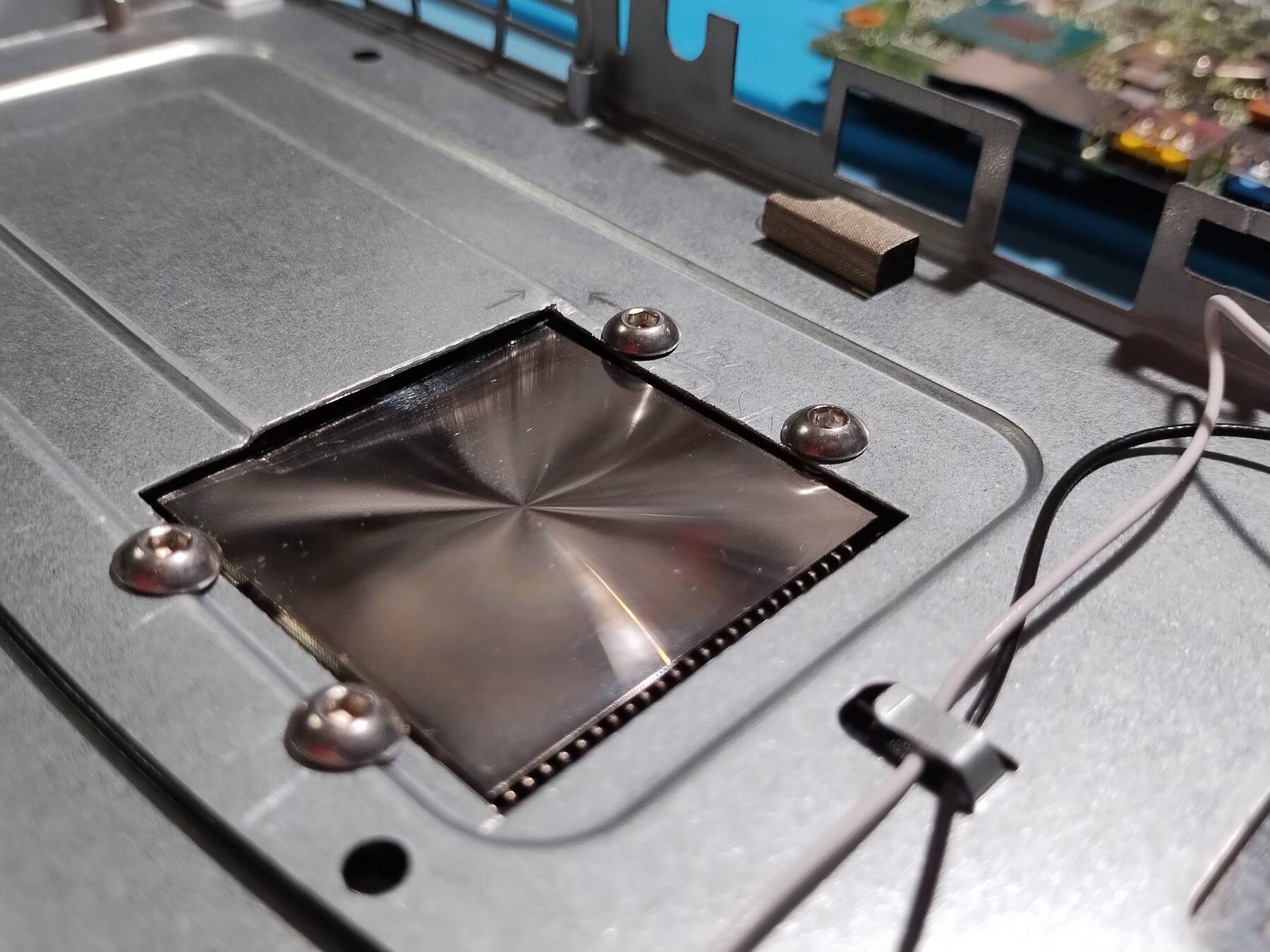
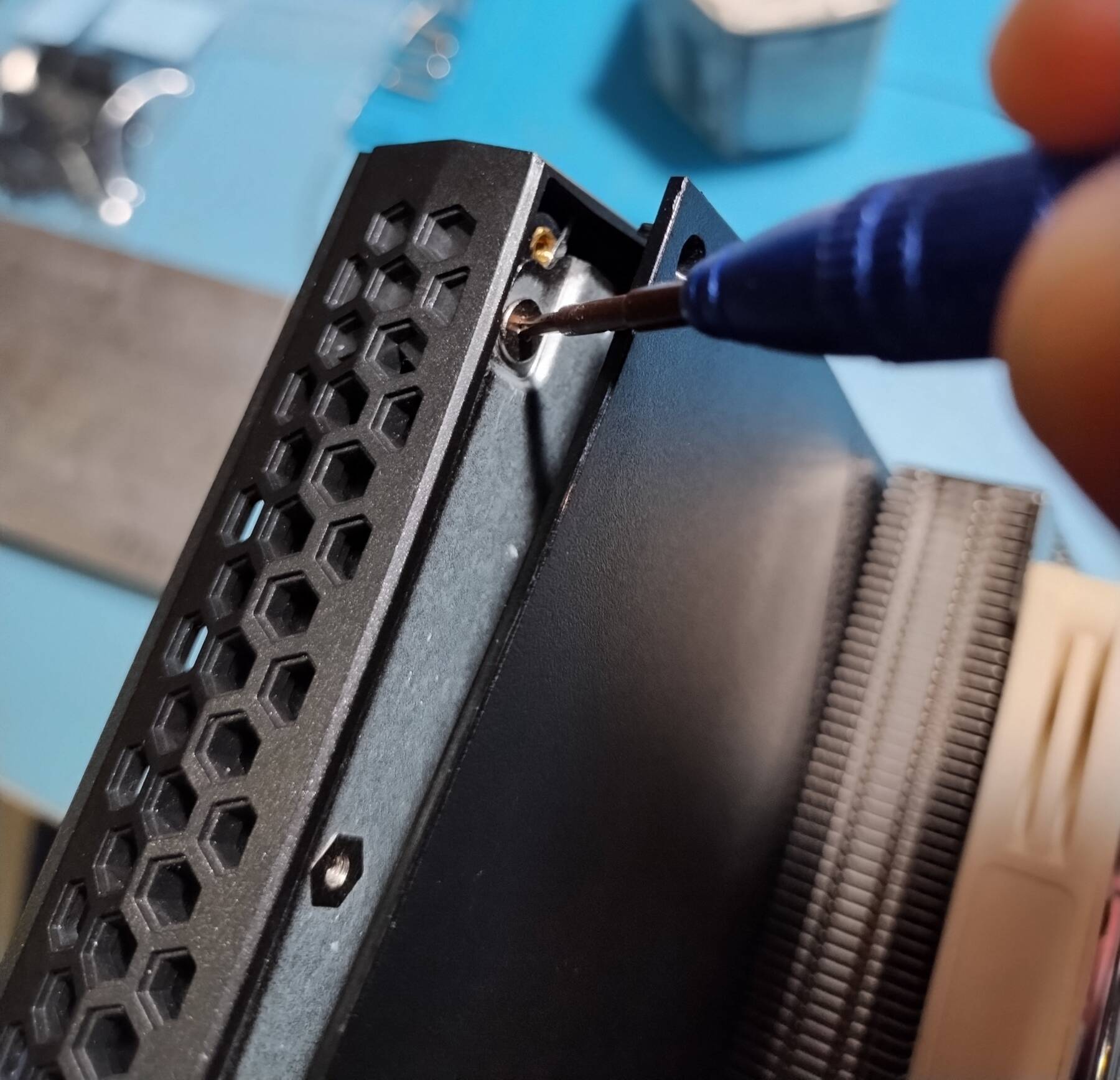
- Mounting holes
I marked the heatsink mounting holes using my paper template and a scribe. Some ended up on the bent portion of the chassis, but I just drilled them at an angle.
I tried mounting it with the orginal hardware, and I think it would actually go pretty well. However, it does not leave space between the heatsink and the chassis for the plastic lid.
- Making room for the NUC plastic lid
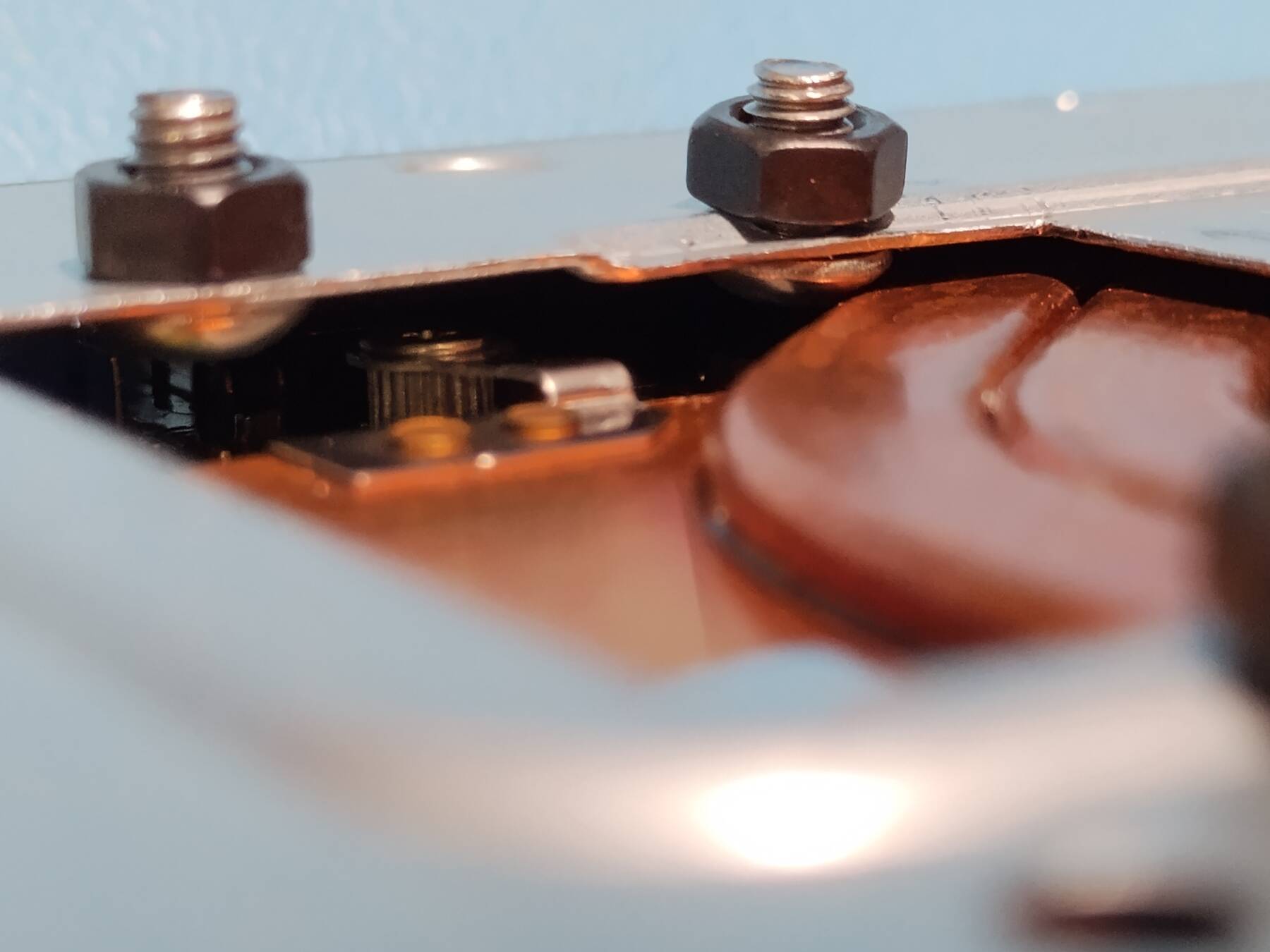
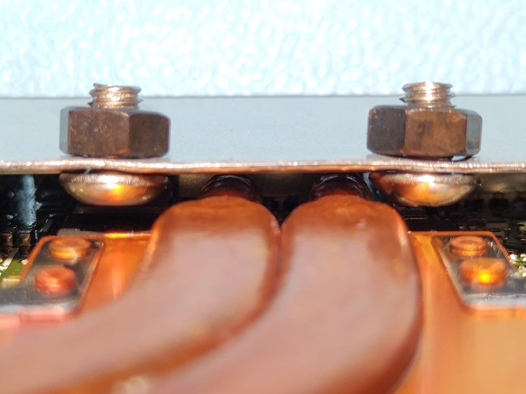
If I want the plastic lid to fit without cutting a massive hole to clear the whole heatsink I'll need to shim things.
I put a Phenom heat spreader on there just to see. It would be nice, but the back side has a cavity. Instead I'll probably resort to stacking some 1mm copper shims.
I might also stack something on the empty portion of the stock heatsink plate so that the Noctua can't tip to the side.
This way I just need to cut a much smaller hole in the plastic lid.
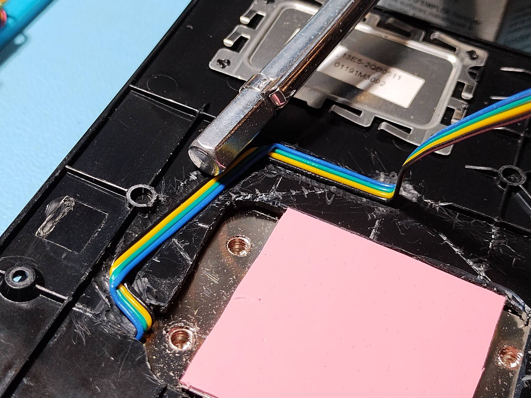
- How am I going to power the fan?
I took a break and decided to think about the fan solution. The NUC seems to lack a 12V rail completely. I tested the Noctua NF-A9x14 PWM fan at 5V, and it runs. It had trouble starting one time, but it seems to have some smarts to restart itself. Current draw is extremely low at 5V. Even though it is rated 0.21A, the starting draw was only around 0.04A, and it runs at 0.02A.
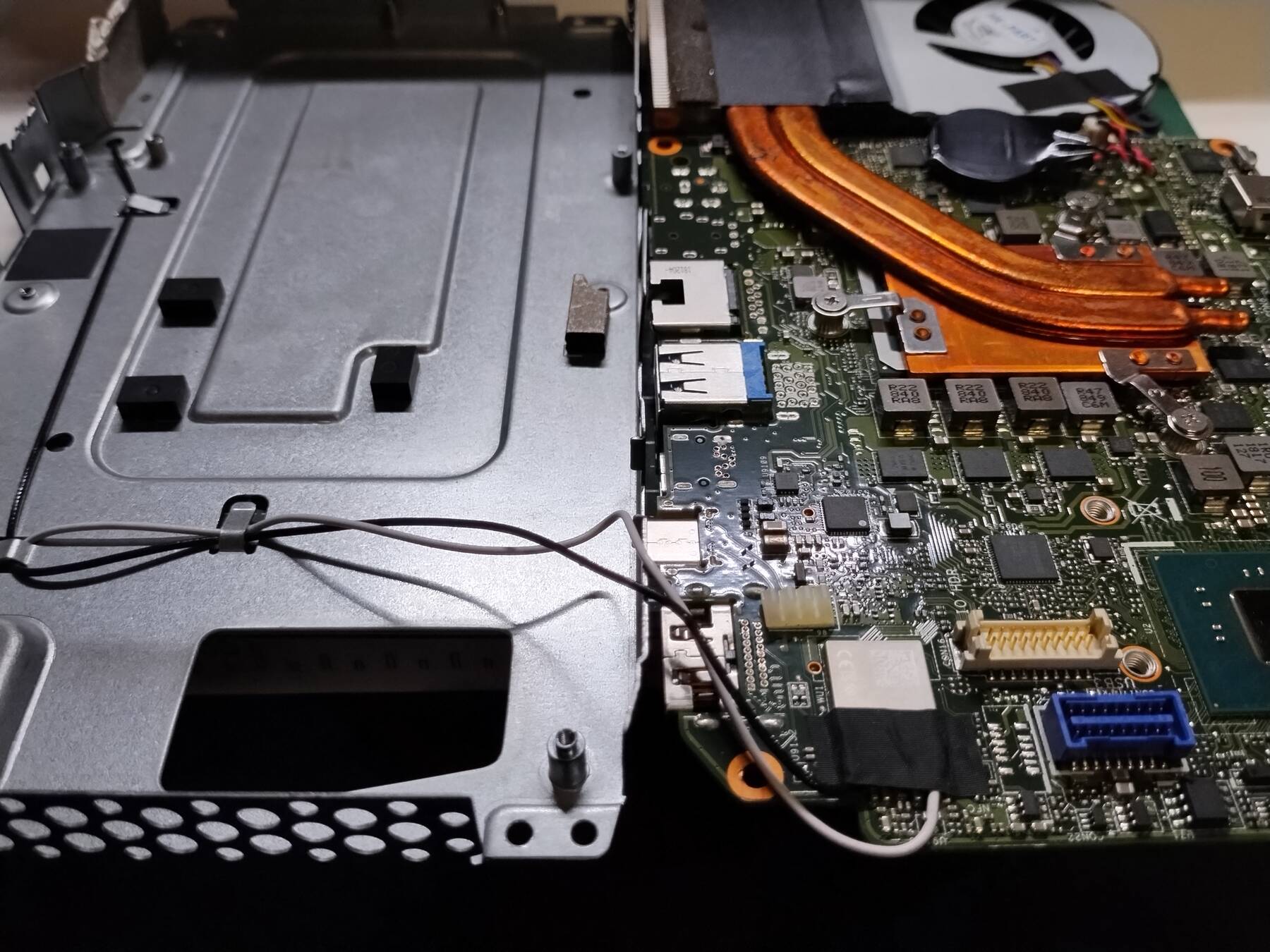
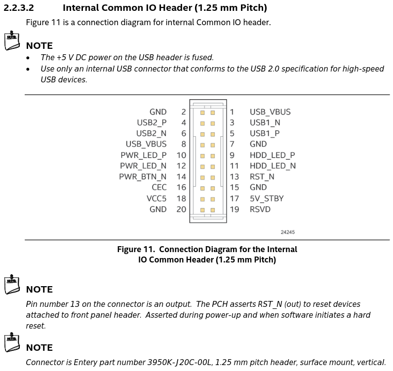
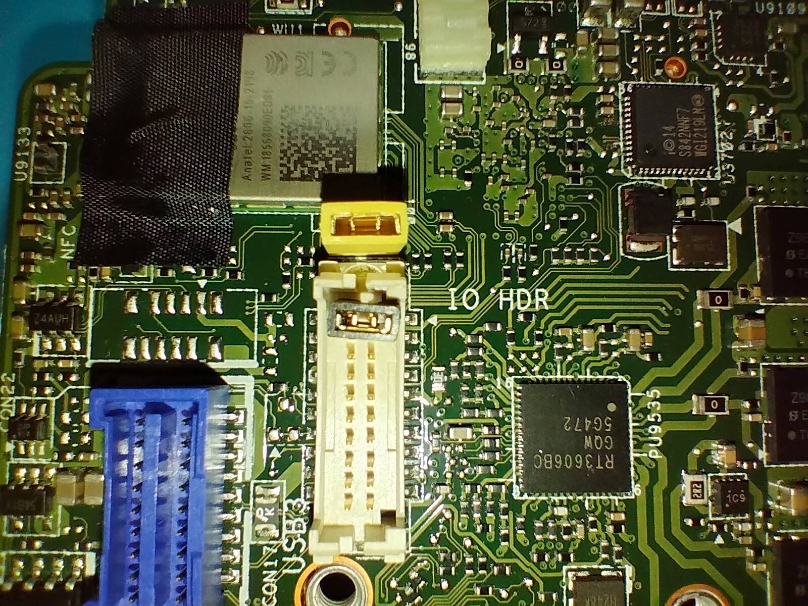
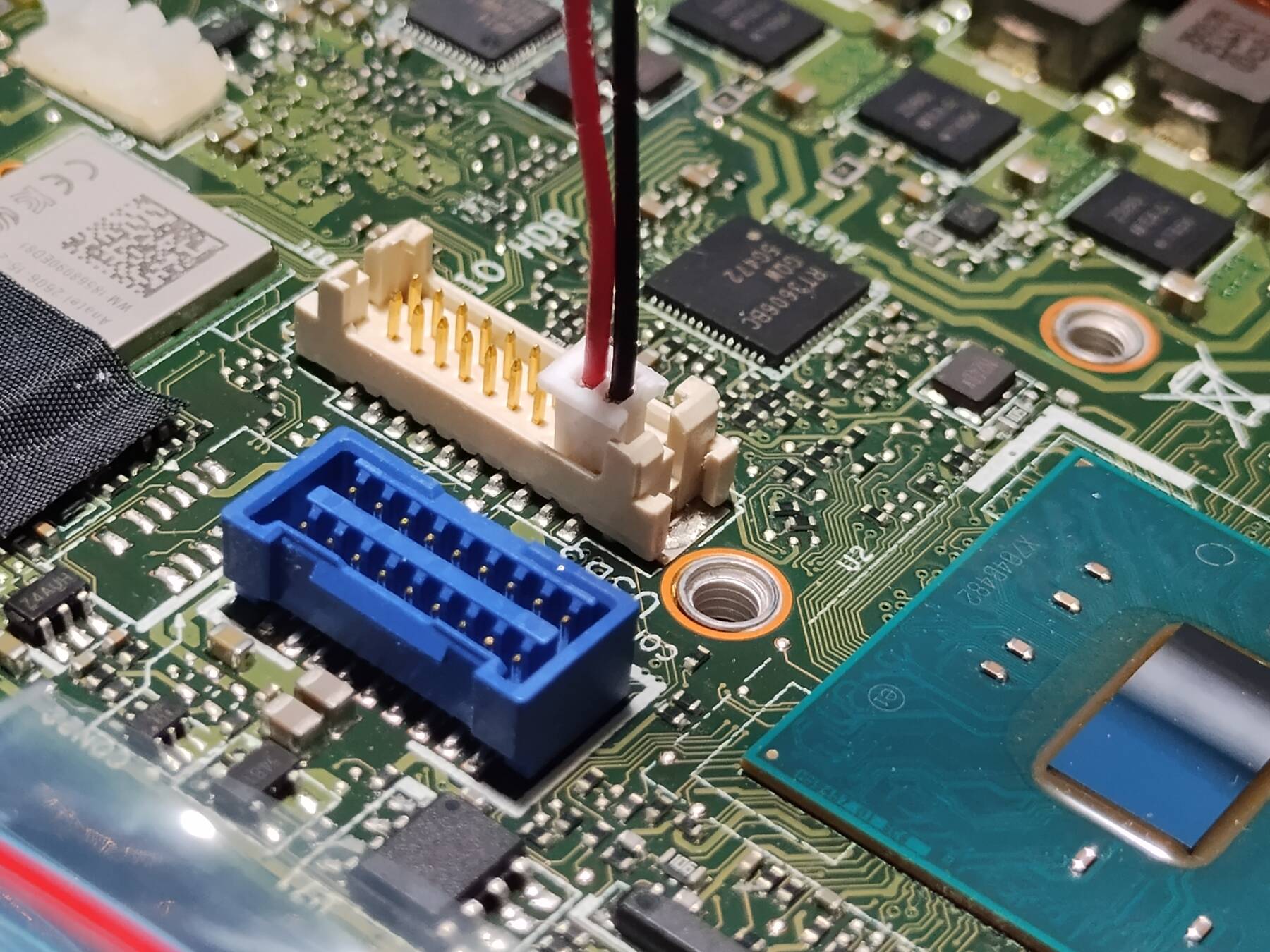
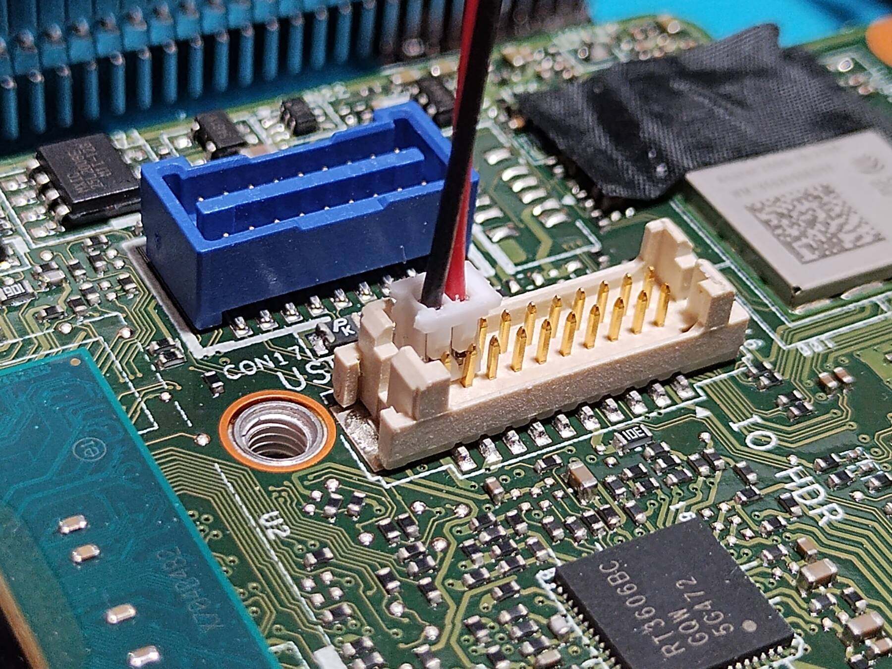
My plan is to run the cable under the lid, into the case, to the "Common IO Header", and get 5V there. I might have to trim the inside of the back of the lid to make space.
Stopping here. What is left from the last plan:
- pull the stock heatsink, and re-paste it
- assemble everything with thermal pads/paste
- test with and without fan
What are new tasks:
- Cut out a rectangle in the top plastic cover
- Cut a few copper shims in half to stack on the unpopulated heatsink side
- Fan cable routing and termination
Final assembly might require a bit of trial and error to get the stack height correct.
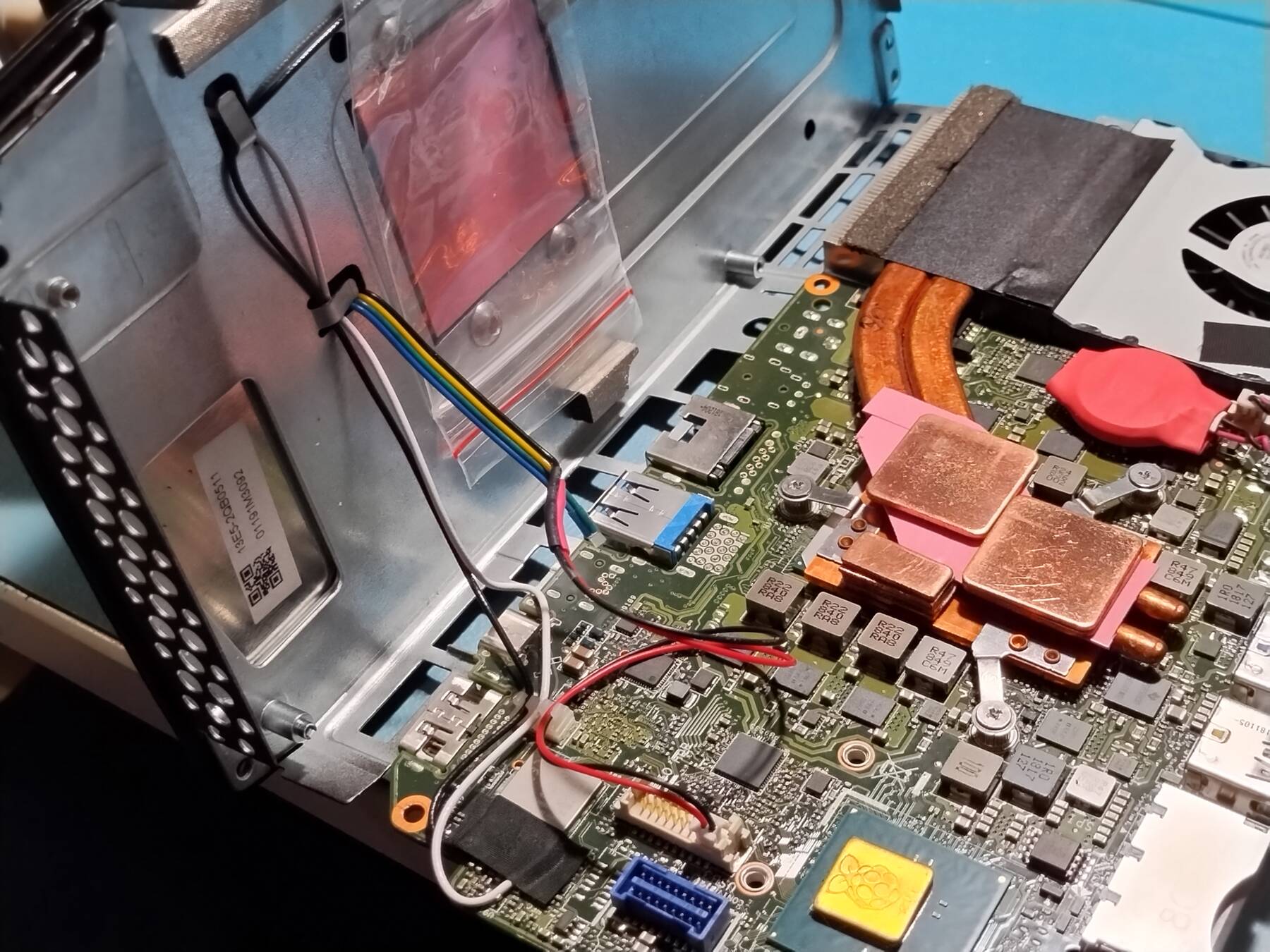
Cooling mod - CPU paste, stack, and fan power
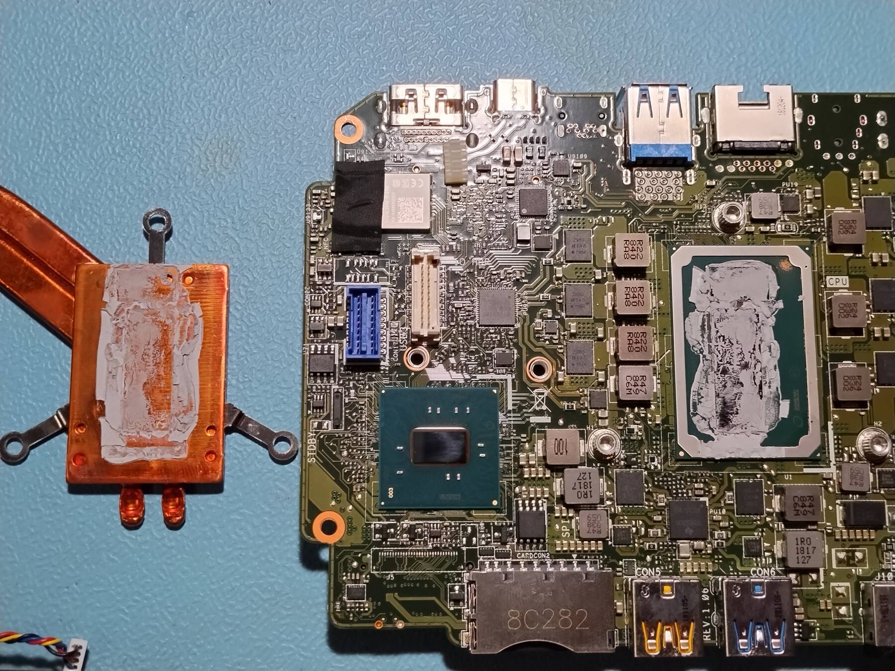
- CPU repaste and stack-up
I repasted the CPU. I forgot to take after pictures. Just imagine a small thermal pad on the little die (top part), and thermal paste on the big one.
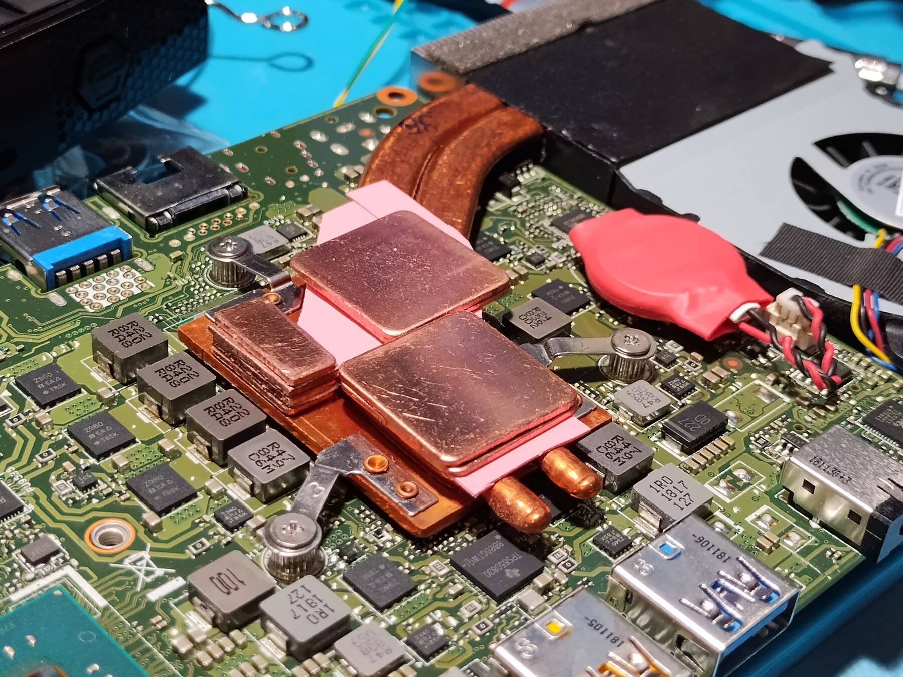
I pasted and thermal padded everything together except the main heatsink surface. It felt like the heatsink was making contact when assembled (the board rocked ever so slightly between stand-offs).
The adhesive shims I cut seemed to work out at a good height so I'm happy with the stack up on the board side.
I started to cut the lid hole out with a coping saw, but I butchered it a bit. I switched to the scroll saw to finish it.
- Fan power solutions
Before final assembly I realized I need to work out the fan cable routing. The header is quite small with 1.25mm pitch. I was expecting 2.0mm, and hoping I could rig something with a couple pin jumpers, but I don't have any that small.
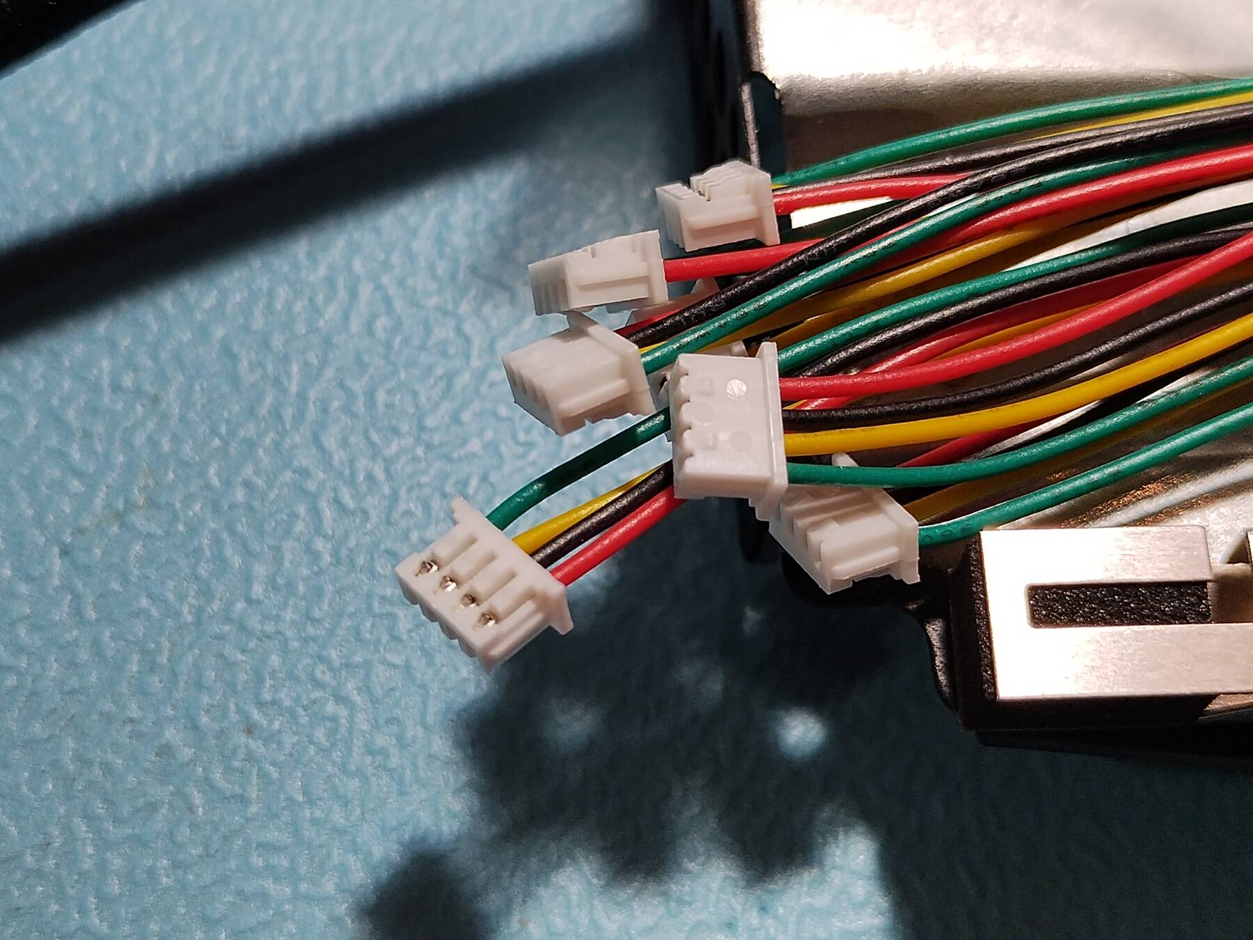
I looked for some 1.25mm connectors, and realized micro-JST is suitable. I have some 4-pin ones so they got cut up. Things are a bit tight, and some pins got pushed out a bit, but it seems solid enough.
Cooling mod - Fan cable routing and final assembly
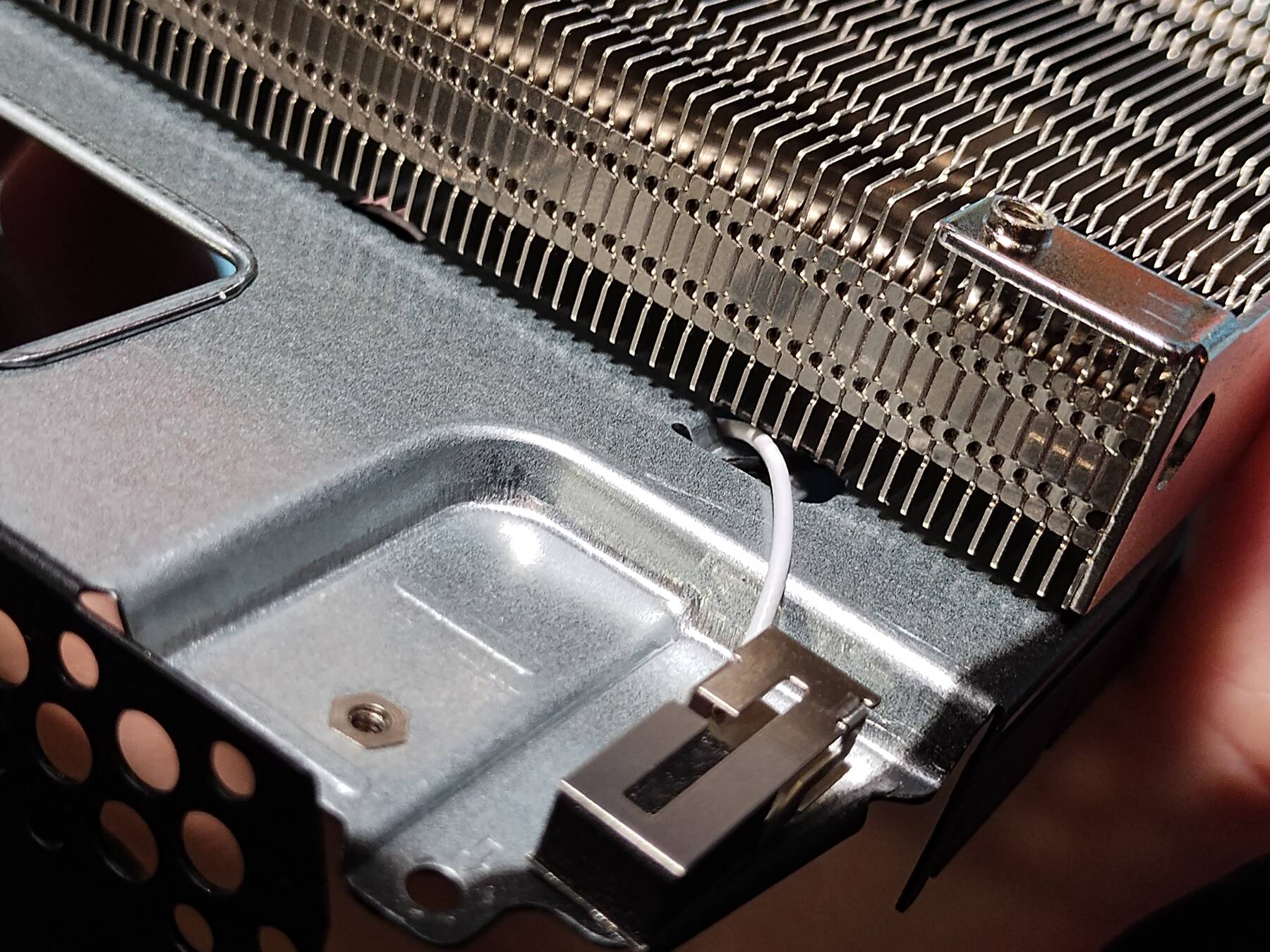
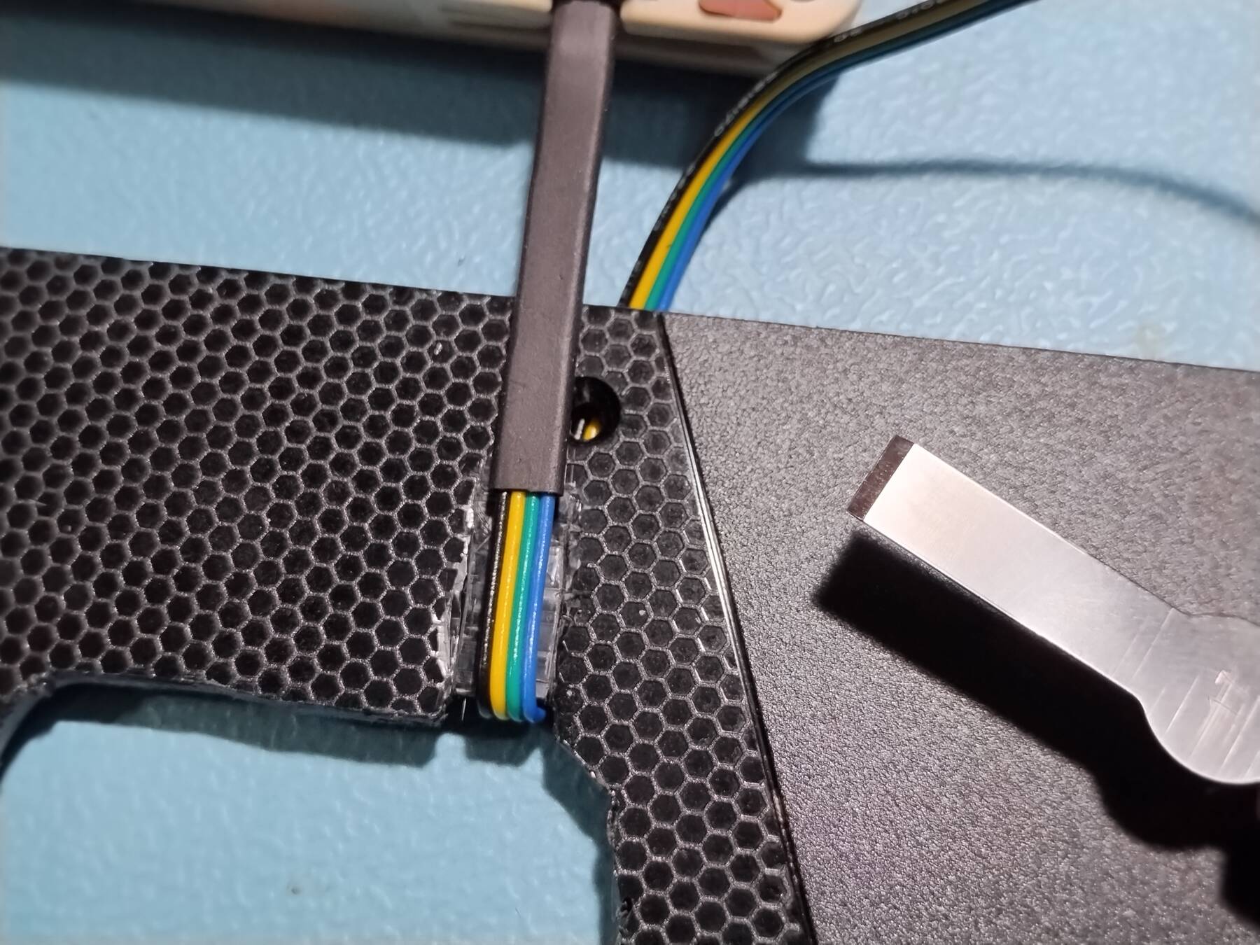
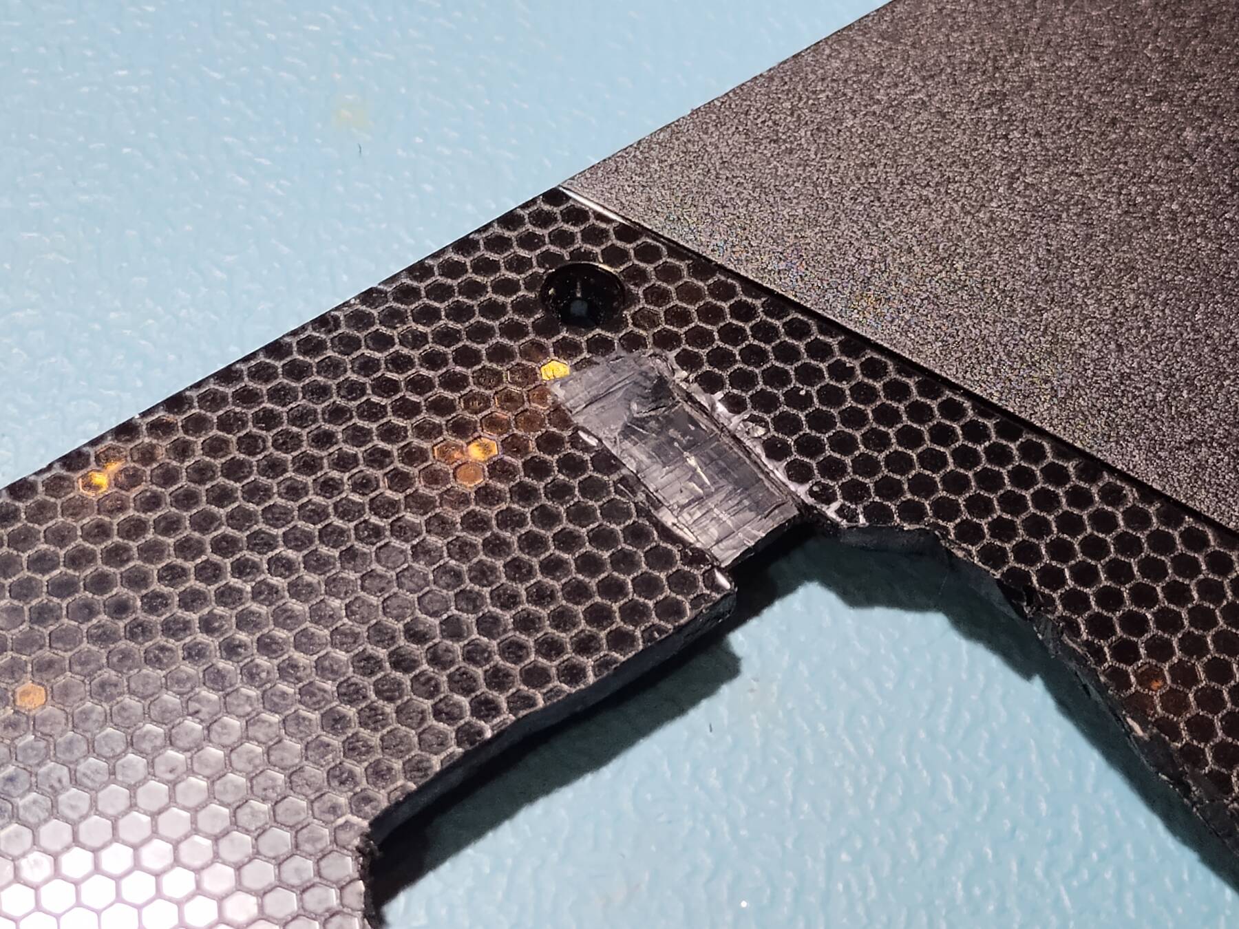
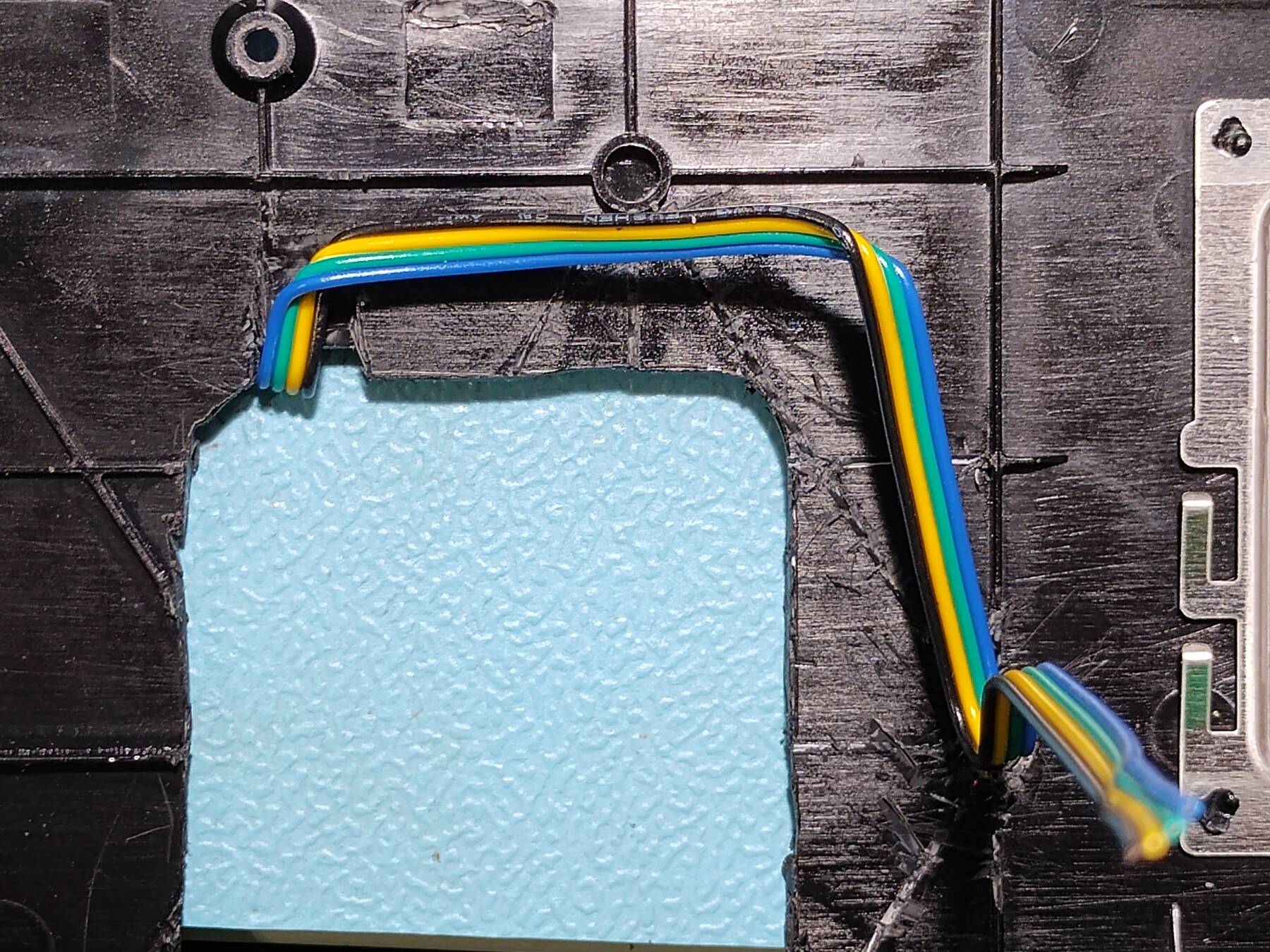
- Fan cable routing
I chiseled a bit out of the lid to wrap the fan cable under the heatsink and pass it through. Some of the support tines under the lid had to be removed to make way. The cable passes into the chassis through one of the WiFi clips. After assembly there was a noticeable bow in the lid. The cable folds were too thick.
I dremeled out a channel inside the lid to make extra room. I used a burr with light passes, and had a pretty good result, but it does throw plastic bits everywhere.
I assembled it, and the motherboard did have some flex when tightening the four corner screws to the standoffs. I think that means there is contact in the center.
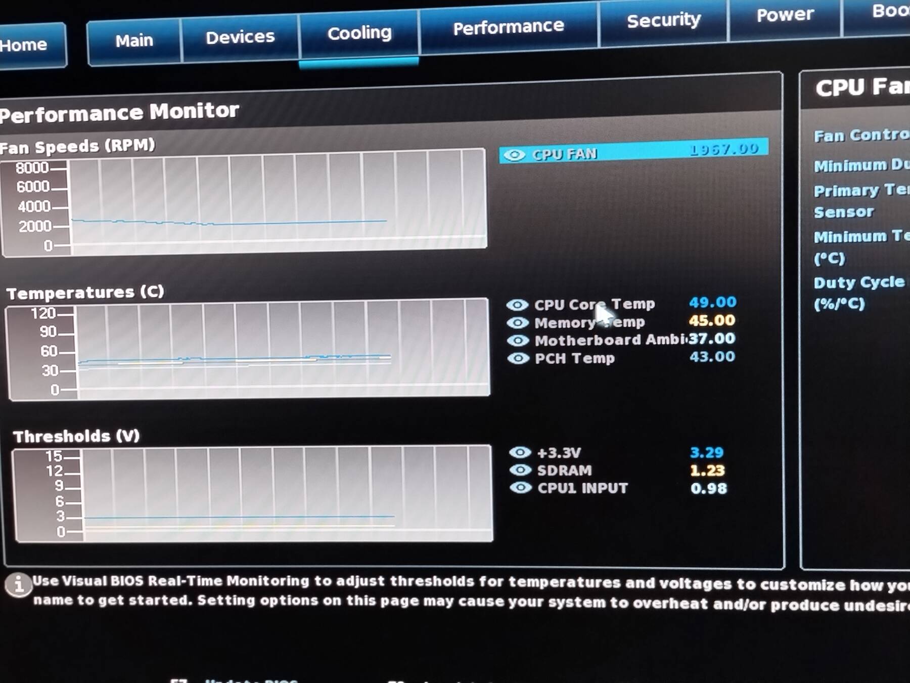
- Initial test
Before disassembling and checking for a pattern in the thermal pad I decided to do a test. Everything powered up, and both fans spin. BIOS temps look good, around 50°C.
In Memtest86+ CPU temps climbed pretty slowly, and seemed to settle around 70°C. Pretty significant drop from 94-97°C. The Noctua heatsink isn't warm at all, but the stock exhaust still outputs fairly warm air.
When I was moving the unit around I saw temps go up to 76°C. I squished the heatsink a bit, and things settled back down to 66°C. So it seems like there's a bit of space, or the heatsink isn't on very parallel.
- Final assembly
I disassembled it. The marks thermal pad marks were minimal, and too light to photograph. I carefully installed the 2 middle lid screws by keeping all the cables threaded through the chassis, and carefully shifting the heatsink around. I flexed the chassis a bit to try to help there be more pressure on the heatsink, but I'll probably just give it another squish during final assembly to help compress the pad.
It was also tricky to attach the plastic port surround to the chassis with the lid already in place. The lid corners had to be flexed up, and the screw driven from an angle.
The final unit weighs 1.09 kg (2 lbs 6.4oz). Previously it was 0.62 kg (1 lb 5.7 oz).
I decided to only test with the fan. It is too tedious to disconnect due to the assembly. Also the internal blower is still the noisiest item. Until I can improve that there is little to gain.
This time, with a good squish and complete assembly, Memtest86+ had a max temperature of 82°C during the first pass (running ~16 minutes).
Ultimately I think this is enough of a noise improvement to run it in the same room as it will be recording, but I've decided to mount it under my desk.
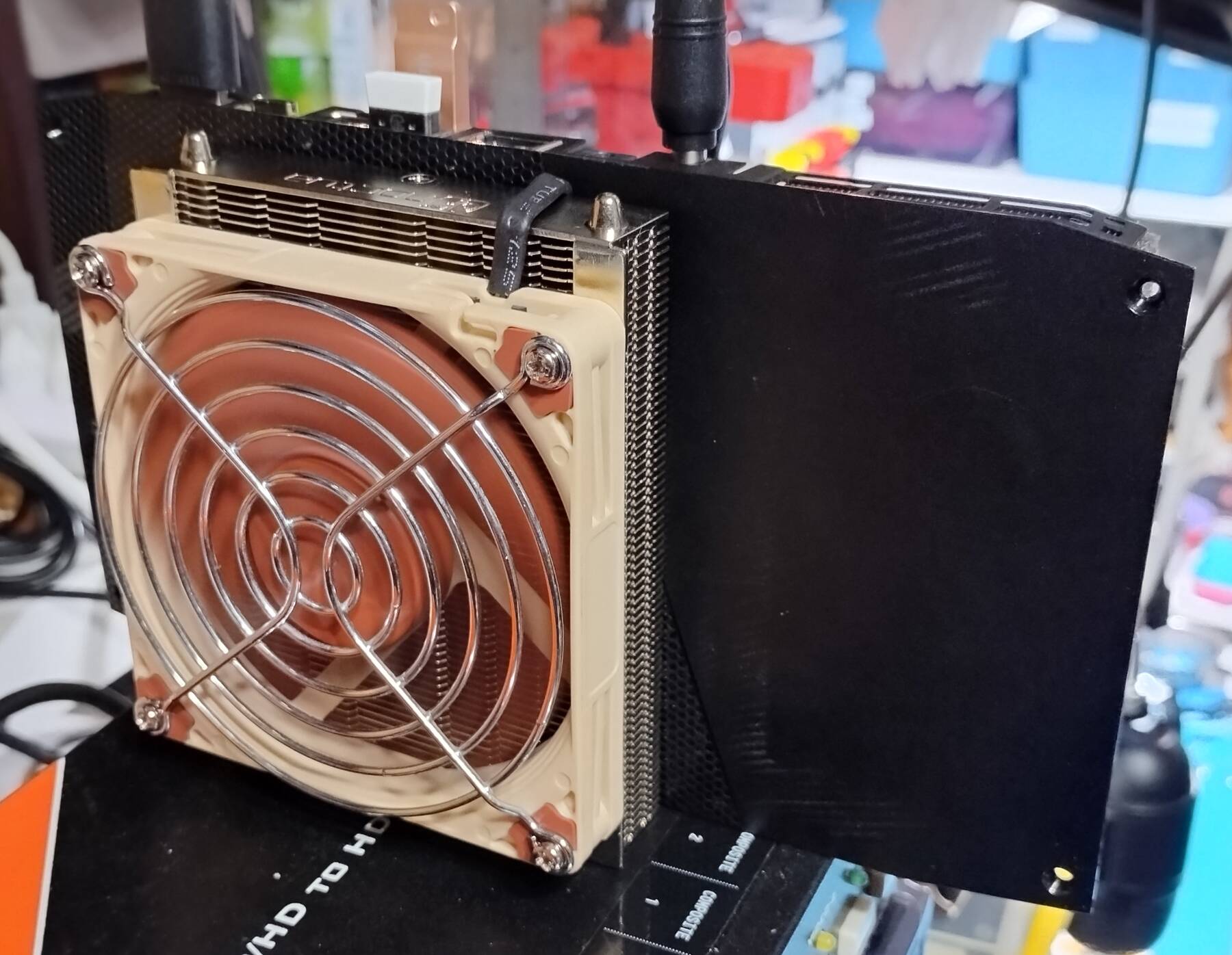
Wall mount and Testing
- Wall Mount
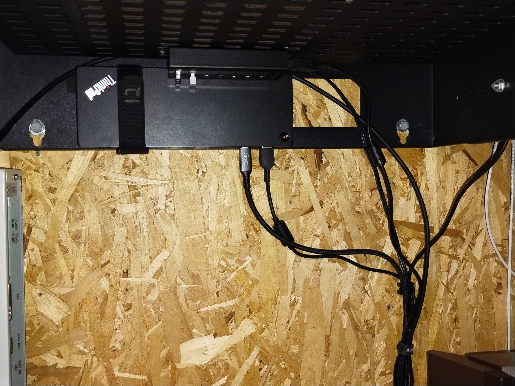
I mounted the Crestron plate to the wall under my desk.
I verified with a power meter that there is no current between the Thinkpad Thunderbolt 3 Dock, and the NUC. I worry a bit about things back-powering other things, but it seems like the NUC and dock combo works well this way.
I also added a 7-port USB 2.0 hub for low speed perphiperals. This might be input devices, MIDI devices, webcams, or other low speed capture devices.
- Firewire thoughts
I'm still working on a firewire solution. I want at least two devices: Focusrite Saffire Pro 14 audio interface, and DataVideo DN-300 DV capture. At the moment I could:
- Install a Firewire card in my Thunderbolt 2 enclosure (2-4 ports)
- Use a Sonnet Thunderbolt 2 to ExpressCard adapter + ExpressCard Firewire card with external power (2 ports)
- Use the Apple Thunderbolt 2 to Firewire adapter with a Firewire hub (3 ports)
In any case I have to use TB3 to TB2 adapter on the dock's front Thunderbolt port. I will also use a interposer board to isolate Firewire power so none of the devices (except maybe the hub itself) will be bus powered.
The TB2 adapter + Firwire hub seemed simplest. From what I read, a TB3 port should be able to supply 15W, and Apple's TB2 to Firewire adapter is good for 7W. My Firewire hub consists of two TI TSB81BA3D 3-port repeaters. These have a claimed typical draw of 120mA 3.3V, and 79mA 1.95V, or roughly 0.55W. Seems like it should work, and I might be able to run a IIDC camera off the spare port.
- Crestron capture device not workable
I went to play more with the Crestron HD-CONV-USB-200, and so far it is a disappointment. I couldn't capture the NUC output, my microscope, or my Samsung camera. Even on a Windows machine I had general trouble with it as a UVC capture device. It seems to present two devices, but some apps seemed to stick on one that only supported 320x180. It did work well in OBS, but was still unfriendly to my camera/microscope.
Back to Linux I tried OBS on my laptop, and I was able to capture its output, but still none of the other devices that I actually want to capture. It is also very slow to initialize. The only other devices I might want to test are my Canon video cameras, but I'm probably just going to set it aside and stick with my Inogeni capture devices for now.
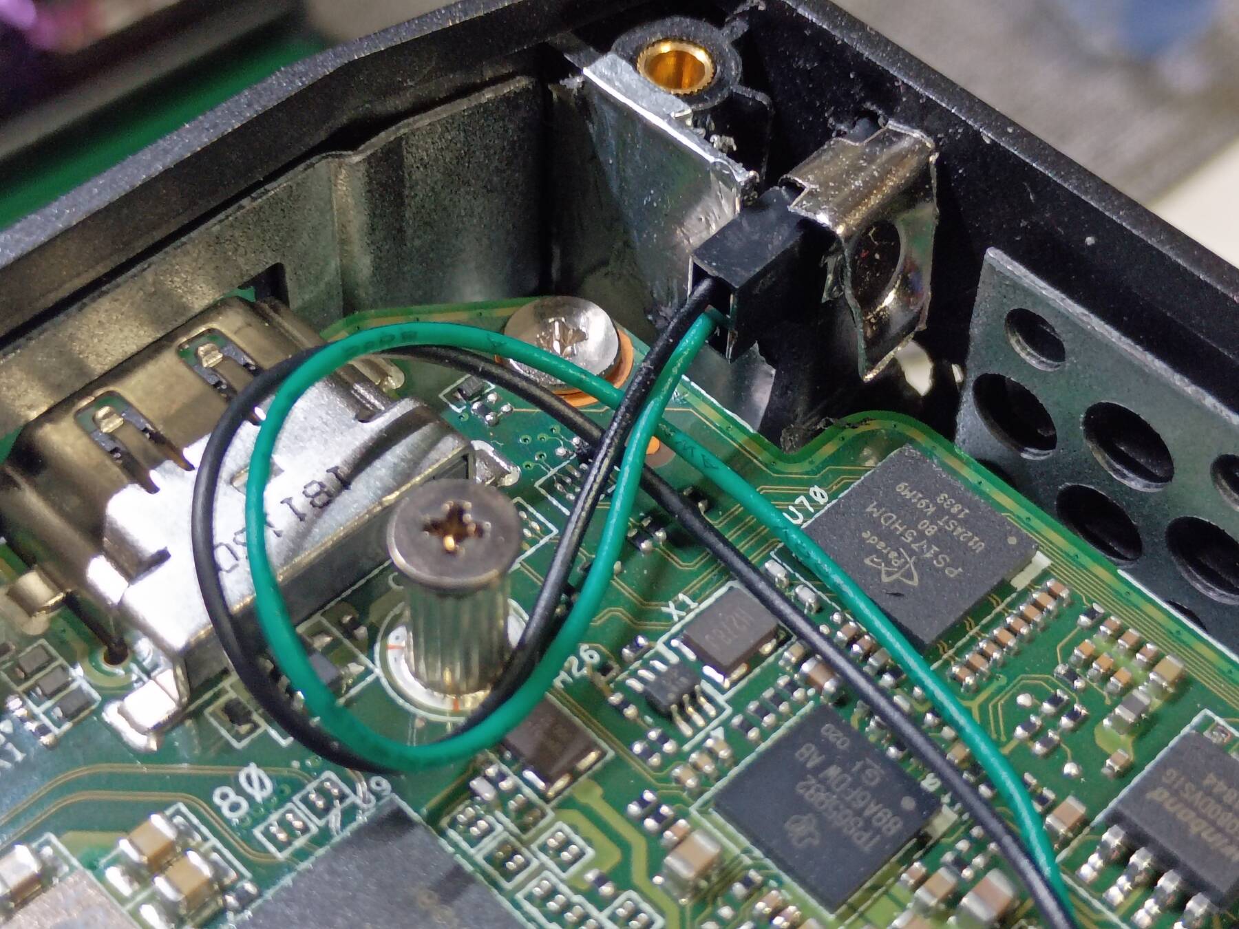
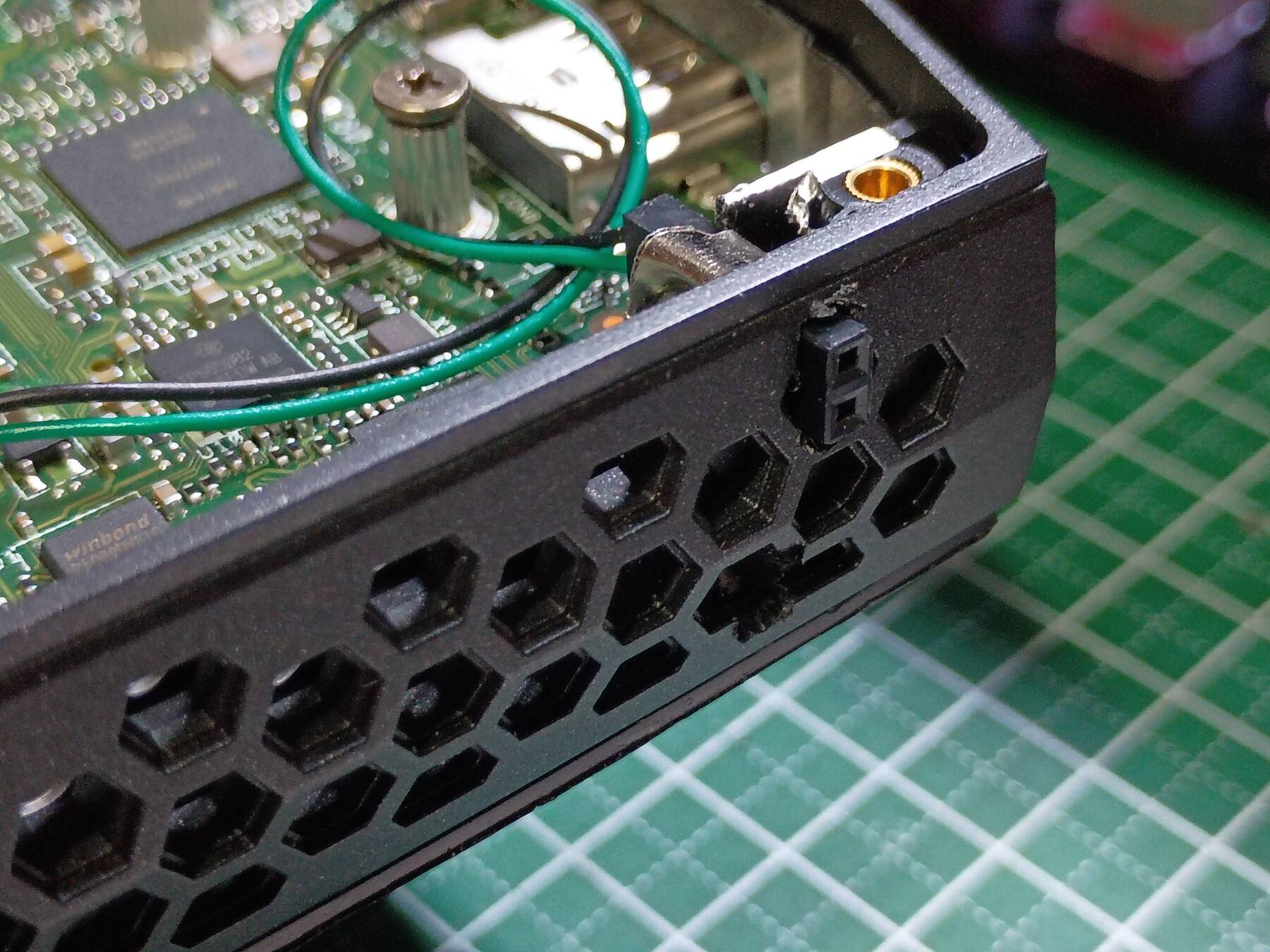
External power button mod
This NUC lives under my desk, but I want a power switch elsewhere. The technical product specs documents the Internal Common IO Header which has a PWR_BTN_N pin.
I used the closest ground for my fan mod, and I didn't feel like rewiring it. This time I just extracted the pins from a JST 1.25mm connector, put some heatshrink on the ends, and plugged them into the pins.
Due to the assembly order I needed the connector on the opposite side of the board, so I passed it through one of the M.2 2242 mounting holes.
Finally I just used a female DuPont connector in the side of the chassis. I fashioned a small metal clip to help hold it in place. I would have glued it, but I think it needs to be removable to ease disassembly.
I forgot to photo the header side before reattaching my heatsink mod, but here is the rest.