Replacing a Sharp 32Q3170U TV Backlight
Table of Contents
Cheap trash TV (dead backlight) repair with parts from another trash TV (busted panel).
This TV appeared to turn on, but I didn't see the display light up. I tried shining a flashlight on the display, but must have missed the location of the logo and input displays. So I went to work taking it to bits.
Disassembly
This is a very optimized design. The TV consists of about 10 layers. Most are clipped together, but there are also a handful of screws.
The layers from back to front are:
- Mainboard plastic cover and speaker housing.
- Combination power/mainboard
- Metal chassis
- LED strips (2)
- Reflector plastic sheet
- Diffuser plastic sheet
- Thinner diffuser plastic sheet
- Plastic edge tray
- LCD
- Bezel
Starting with the TV on it's face remove 6 black screws, mainboard cover, and speaker housing.
Then the LED, speaker, and display cables can be detached from the board.
With the speakers off the LCD panel circuit board can be unscrewed from the base of the TV. It is also held in place with adhesive foam tape. However, you can wait to detach it until it's time to move the LCD.
Optionally the mainboard can be removed (4 screws), or place plastic cover back on and flip the TV over.
The plastic bezel is held on with just clips, and a metal or plastic spudger works well to pop it off.
Now the LCD circuit board can be unglued, and the LCD glass panel lifted out. Take care not to flex it, and make sure the circuit board flex ribbons clear the frame.
The plastic edge tray is pried out with a spudger (take note of it's orientation for reinstall).
Then the two diffuser sheets can be lifted out together.
Six screws held the reflector sheet in place as well as a small peg at the top and a bit of tape at the bottom.
With it removed the strips are now accessible for testing. Note: they are well glued in place. If you want to remove them without bending up the strips it'll probably require heating to loosen the glue.
Testing original strips
I put my meter in diode mode and began probing the test points, however none of the LEDs would light. I set up my bench supply to deliver around 18V with the current limit all the way down.
I attached it to a single strip and ramped the current up slowly. In my test I only saw two LEDs light faintly, and then they never lit again. If these strips were working at all I put a stop to that.
The circuit
I didn't analyze things very deeply. I noted the board had a On-Bright OB3353A PWM controller. The 30V maximum gave me an upper limit on about how many LEDs could be in series.
This controller relies on signaling to an external mosfet to actually control the current.
The backlight itself is very simple. Two strips of six LED packages are in series. Each package appears to have two LEDs in parallel. While I couldn't test the dead LEDS properly, the circuit board mentioned 2X6 which I think confirms this configuration.
Replacement strips
I had some LED strips from a Vizio V705-J03. These are two-piece strips designed to be driven with opposite direction current. That is only one half of the strip can be lit at a time (but this happens super fast). It may also have been driving the strips independently allowing for zone brightness control.
I tested them on a current limited supply to start lighting at about 15.5V 10mA.
I placed them in series just like the original strips. What differs is these are single diode LED packages while the original strips appeared to have two diodes per package. I was worried they would be over-driven so I opted to use a second pair of strips (four total) in parallel.
I wired them up as-is for a test. Just a bit of masking tape to hold everything in place. It looks like this:
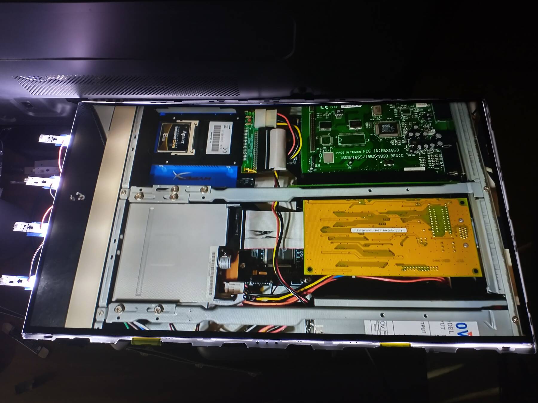
Figure 1: Testing the panel with too long LED strips
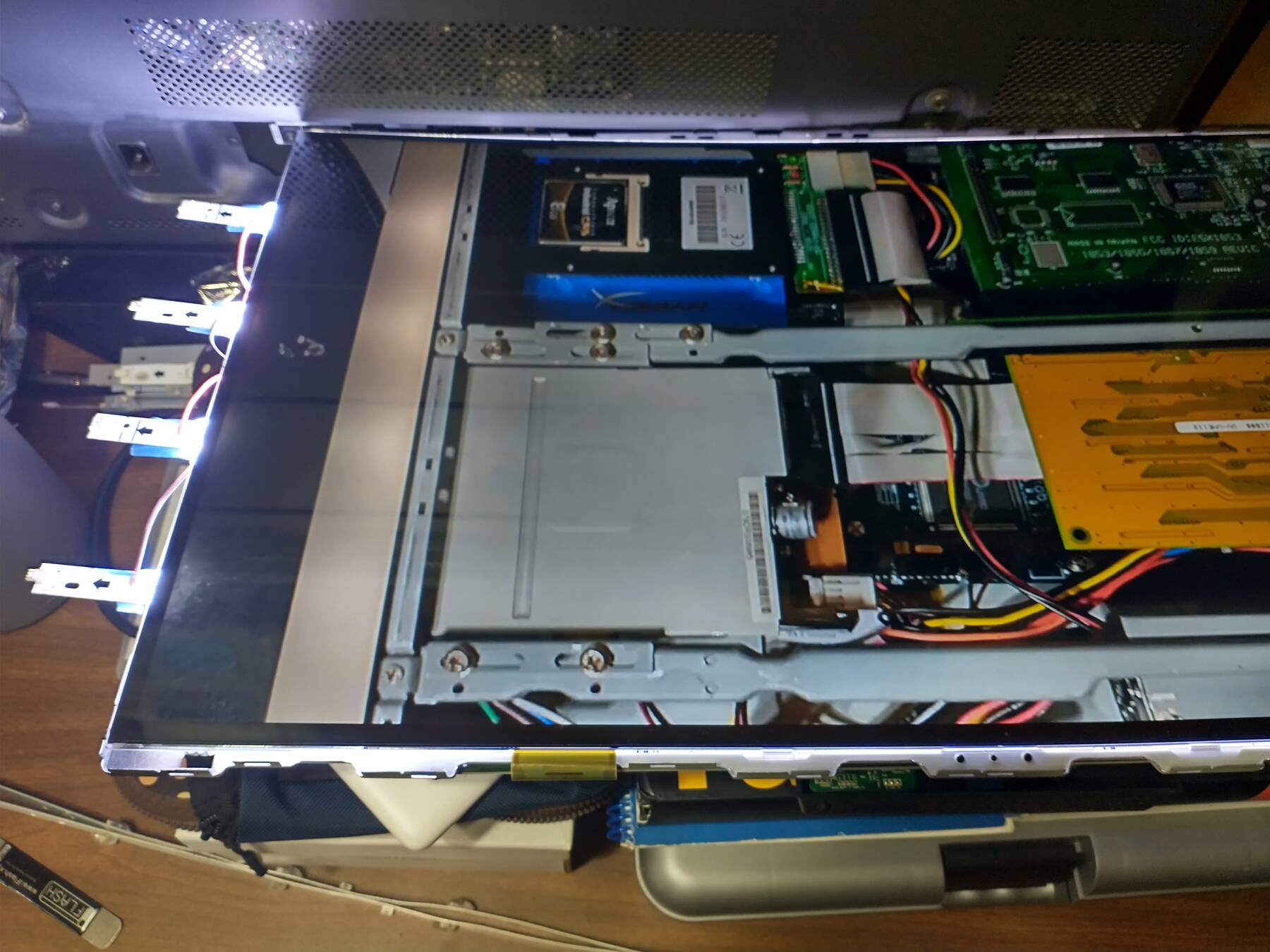
Figure 2: Testing the panel with too long LED strips
After a couple hours test, and the strips being barely warm I was satisfied to start fitting them "properly". I cut the strips' length down to just outside of the solder points. See Cutting aluminum circuit boards for the issue with modifying aluminum PCBs this way.
Then each strip was attached with 3M 300LSE double-sided acrylic adhesive tape. The ends had to be slightly bent, but to avoid breaking the LED reflectors off I only bent them about an inch away from the final LED.
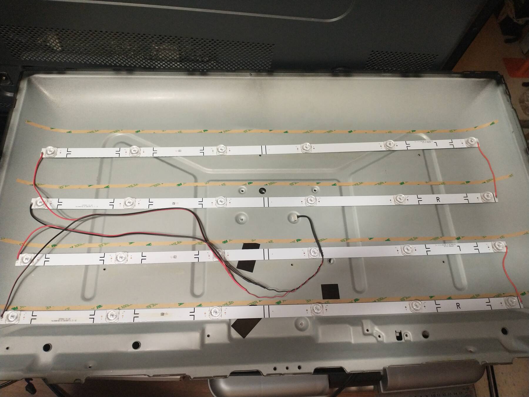
Figure 3: Preparing to install the new LED strips
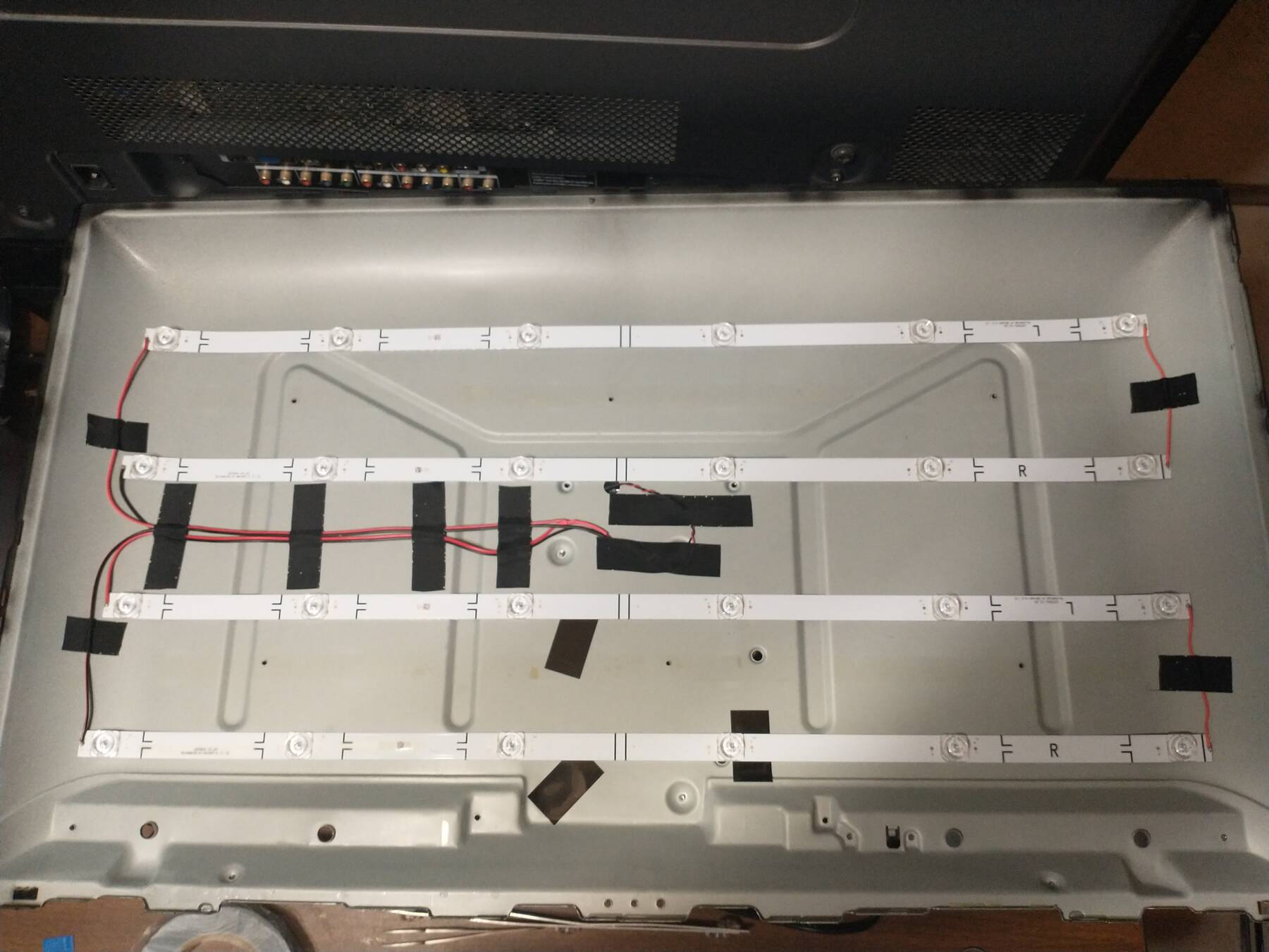
Figure 4: The new strips installed, and wiring taped down
After verifying the aluminum PCB back and copper traces were still not shorted (from the cutting process) I taped all the wiring down. I did note that the chassis is bonded to the negative connection by the TV mainboard, but I just tested with the backlight unplugged to ensure isolation.
The reflector needed modification for the new LED positions. I used a flashlight shining through the old holes, and a sharpie to mark the new LED locations. Then I traced a bunch of circles and cut them out with a craft knife.
Here you can see how the new LED positions encroach on the angled portion of the reflector. I made some notes about positioning: Bright spots.
Unfortunately there wasn't much I could do with these slightly long strips as it would change the number of LEDs in series to cut them any shorter.
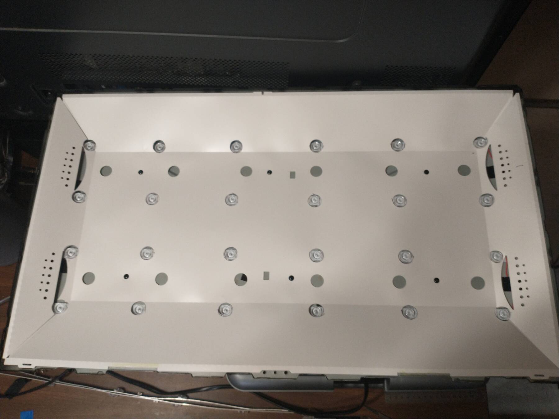
Figure 5: The modified reflector sheet fit in place
Unforeseen consequences
The repaired backlight is always on.
This could be a previous fault in the circuit, and potentially why the LEDs failed. Perhaps the mosfet is defective, and always passes current.
Perhaps the mosfet is fine, and always passed that amount of current, but it wasn't enough to light the stock strips. That the backlight get's brighter when the TV is actually on supports this theory.
My other idea is that the circuit design relied on some characteristic of the LED string to determine "off", and some component values might need to be selected differently now.
Once I get a remote I can hopefully adjust brightness, and see if any behavior confirms a particular theory.
Takeaways
Cutting aluminum circuit boards
I used a sheet metal nibbler to trim the LED strips aluminum PCB. This drove the copper layer against the backing causing a short. In measuring I saw readings in the kilohms and megohms so contact was minimal, but I still wanted there to be complete separation.
It took some careful filing, and breaking off copper bits to ensure there was no short.
Ideally any board being trimmed would have the copper removed in that area, but that wasn't an option here. It might have been possible to reverse the nibbler for better results. This way the blade would drive the aluminum into the copper, but it wouldn't deform into the material like the copper layer did. Otherwise a rotary cutting tool might be more suitable.
Bright spots
I used four strips to make up for the dual LED packages of the original two strips. Also my strips' 6 LEDs were spaced wider than the originals. This pushed the LEDS towards the screen edges, and I consider it a mistake.
I now think it's best to keep any new LEDs inside the flat reflector area. Having LEDs in the angled portions resulted in definite bright spots that are noticeable on any solid dark images.
It was hard to take a nice picture, but on the right side you can sort of see the effect of the bright spots.
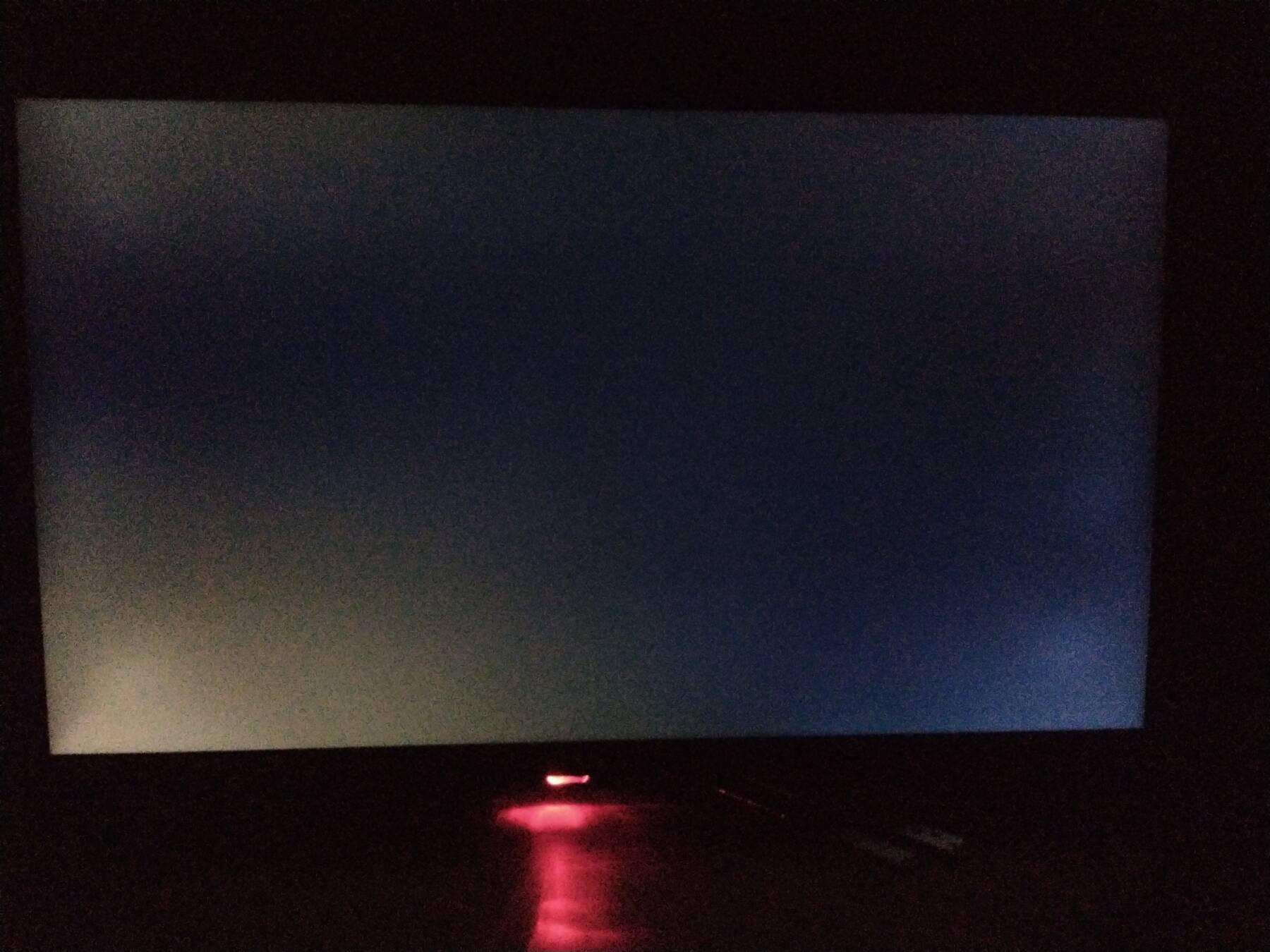
Figure 6: The screen in it's off state
However, in a bright and busy image it's hardly noticeable.
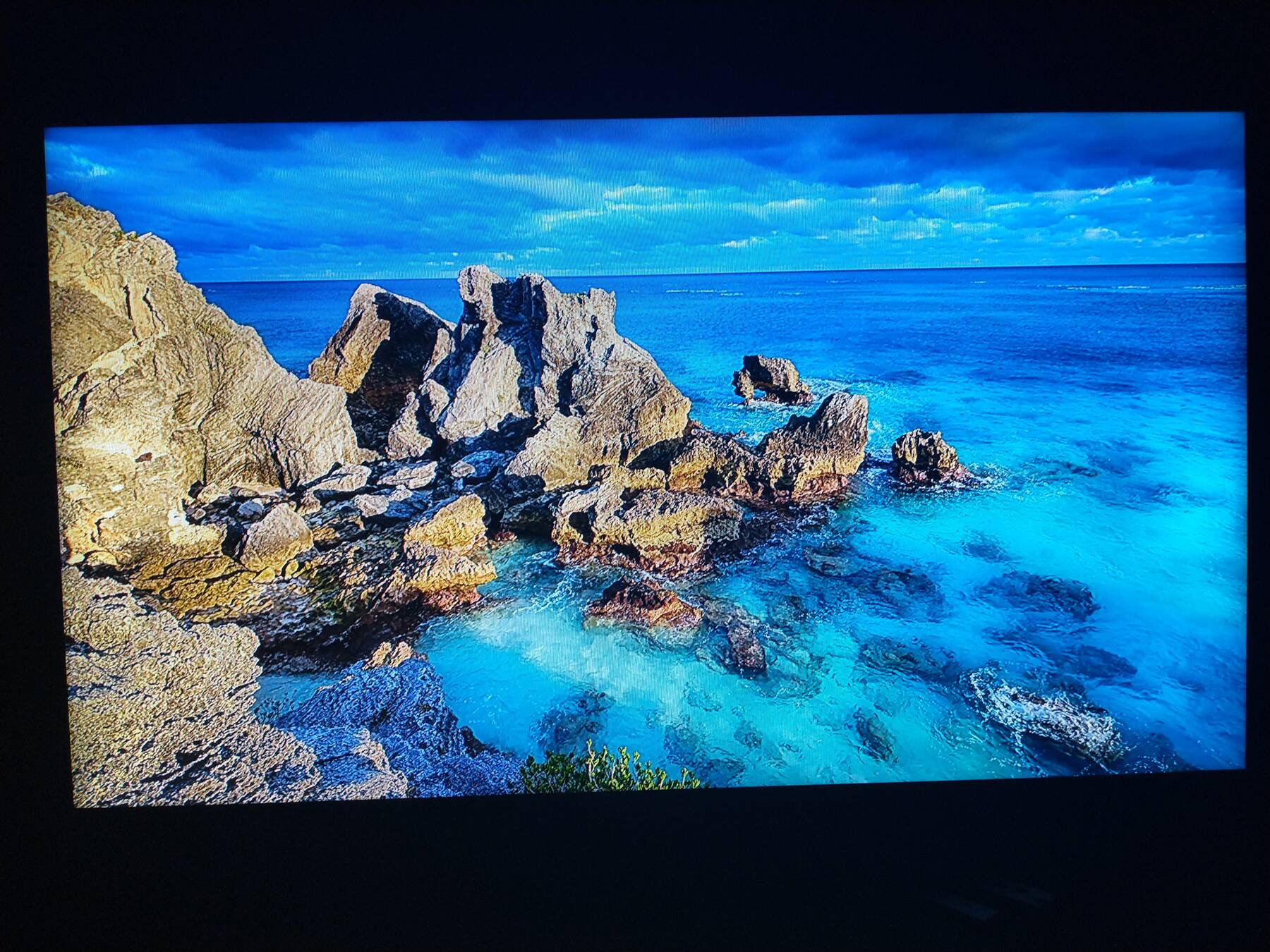
Figure 7: Displaying a chromecast image